Rotary cylinder dryer for high-pressure airflow sludge scattering device with sprouted bed

A technology of high-pressure air flow and spouted bed, which is applied in dehydration/drying/concentrated sludge treatment, grain treatment, etc., can solve the problems of decreased drying output, low thermal efficiency of dryer, and difficulty in meeting actual needs of processing capacity, and achieves the goal of drying Increased dry output and good dispersion effect

Active Publication Date: 2017-06-30
FOSHAN FENGHUI MACHINERY
View PDF9 Cites 2 Cited by
  • Summary
  • Abstract
  • Description
  • Claims
  • Application Information

AI Technical Summary

Problems solved by technology

During the drying process of municipal sludge, the on-site sludge has the characteristics of high moisture (water content 75-85%), high viscosity and rich in nutrients; due to its special physical and chemical properties, it is It is easy to cause agglomeration, sticking to the wall, and incomplete drying at one time; it leads to low thermal efficiency of the dryer and a decrease in drying output; as the amount of sludge drying increases, the processing capacity of the existing drying method is difficult to meet the actual needs ; To solve the above problems, it is necessary to quickly break up the high-moisture and high-viscosity sludge entering the dryer, and break up and disperse some of the large particles that are agglomerated to increase the contact between wet materials and hot air. The contact area enhances the heat transfer efficiency and facilitates the drying of materials; at present, the most effective in the rotary drum dryer is the built-in mechanical dispersing device, that is, the through-shaft dispersing device; the through-axis dispersing device is the dispersing device Cross the entire cross-section along the axial direction of the rotary drum dryer; along the radial direction of the rotating shaft, radial breaking teeth are installed; both ends of the shaft are fixed and installed by bearings and corresponding brackets, and the rotating shaft is located in the middle of the dryer , not in contact with the cylinder of the dryer; the loose teeth are installed on the rotating shaft inside the dryer by welding or bolting; the rotating shaft rotates at a high speed driven by the drive pulley installed at one end; if figure 1 As shown, the shaft-type dispersing device includes a dispersing rotary drum dryer 1, and a wet material 2 connected to the dispersing rotary drum dryer 1, a combustion furnace 3 and a cyclone separator 4; The drum dryer 1 is equipped with a rotating shaft 5; the other end of the cyclone separator 4 is connected to the system induced draft fan 6; when the drum dryer is working, the wet materials in the dryer are continuously scattered on the rotating and breaking up device , and is strongly impacted and dispersed by it, so as to achieve the effect of dispersing. The advantage is that this form of dispersing device can play a dispersing effect in the entire dryer cylinder, so the dispersing effect is better; but because The rotating shaft traverses the entire tumble dryer, which is always in contact with high-temperature hot air and materials, and the temperature of the rotating shaft rises rapidly; in order to avoid damage to the shaft end bearing due to high temperature, the rotating shaft is usually selected as a hollow shaft, and the rotating shaft is hollowed out. Circulating cooling water is introduced into the cavity to reduce the temperature of the rotating shaft and prolong the service life of the bearing; this brings about the following adverse consequences: 1) Due to the cooling water, it will take away part of the heat in the rotary drum, and the heat loss will increase; Due to the limitation of shaft strength and moment of inertia, the length of the dispersing device cannot be designed too long. Generally, the length does not exceed 20m. Therefore, the use of tumble dryers is also limited, and it is only suitable for small and medium-sized drying equipment.

Method used


Image

  • Rotary cylinder dryer for high-pressure airflow sludge scattering device with sprouted bed
  • Rotary cylinder dryer for high-pressure airflow sludge scattering device with sprouted bed
  • Rotary cylinder dryer for high-pressure airflow sludge scattering device with sprouted bed

Examples


Embodiment Construction

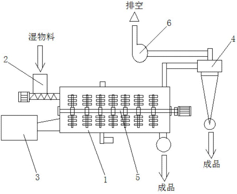
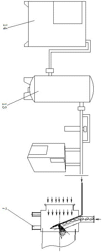
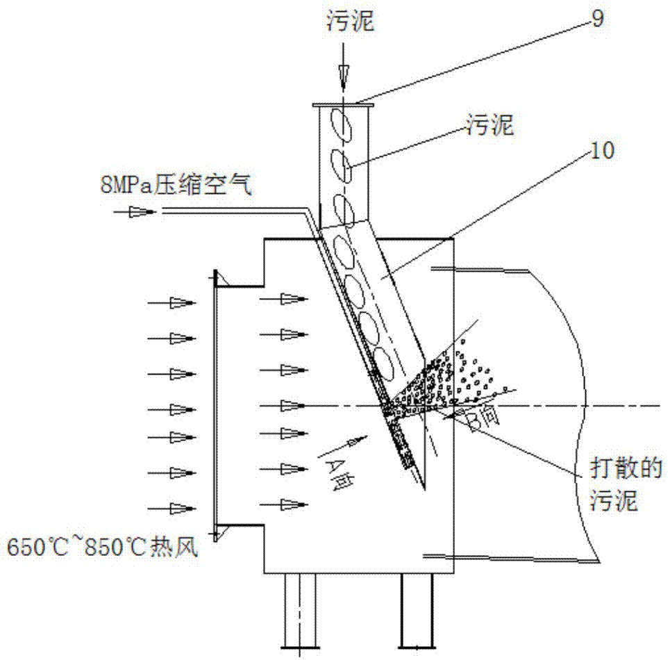
[0020] Such as Figure 2 to Figure 5 As shown, the rotary drum dryer with a spray bed high-pressure airflow sludge dispersion device of the present invention includes a dryer 7; the dryer 7 includes a rotary drum 8; the top of the rotary drum 8 is provided with sludge Inlet 9; the sludge inlet 9 extends into the rotary cylinder 8 through the sludge chute 10; the bottom of the sludge chute 10 is provided with a spouted bed; the rear side of the spouted bed is equipped with a high-pressure air chamber and a high-pressure air pipe; The high-pressure air pipe is composed of a high-pressure air main pipe 11 and a plurality of high-pressure air branch pipes 12 connected with the high-pressure air main pipe 11; the high-pressure air main pipe 11 is connected with the compressed air machine 14 through the air storage bag 13; the sprayed bed is composed of It includes first to bottom spouted beds 15, second spouted beds 16 and third spouted beds 17 in order from top to bottom; multiple...


PUM


Abstract

The invention discloses a rotary cylinder dryer for a high-pressure airflow sludge scattering device with a sprouted bed. The rotary cylinder dryer comprises a dryer body, the dryer body comprises a rotary cylinder, a sludge inlet is formed in the top of the rotary cylinder and extends into the rotary cylinder through a sludge chute, the sprouted bed is arranged at the bottom of the sludge chute, a high-pressure air chamber is formed in the rear side of the sprouted bed, air is supplied for the high-pressure air chamber through a high-pressure air pipe, the high-pressure air pipe comprises a high-pressure air main pipe and a plurality of high-pressure air branch pipes connected with the high-pressure air main pipe, the high-pressure air main pipe is connected with an air compressor through an air storage bag, the sprouted bed sequentially includes a first sprouted bed, a second sprouted bed and a third sprouted bed from top to bottom, and the high-pressure air branch pipes are connected with the first sprouted bed, the second sprouted bed and the third sprouted bed. The rotary cylinder dryer is good in scattering effect, and test operations show that the drying yield of an original rotary cylinder can be doubled.

Description

technical field [0001] The invention relates to a rotary drum dryer with a spray bed high-pressure airflow sludge breaking device, belonging to the technical field of dryers. Background technique [0002] The main body of the rotary drum dryer is a slightly inclined drum that can rotate. The wet material is fed from one end of the drum. When passing through the drum, it is effectively contacted with the hot air passing through the drum or the heated wall to be dried; , chemical industry, metallurgy, building materials and other industries are widely used; compared with other drying equipment, rotary drum drying has large production capacity, continuous operation, simple structure, convenient operation, less failure, low maintenance cost, and wide application range. The fluid resistance is small, and it can be used to dry granular materials; according to the heating method of the dried materials, the current rotary drum dryers can be divided into five types, namely direct hea...

Claims


Application Information

Patent Timeline
Patent Type & Authority Applications(China)
IPC IPC(8): C02F11/12B02C19/06
CPCB02C19/068C02F11/12
Inventor 孙亮黄文煜孙超郭光义
Owner FOSHAN FENGHUI MACHINERY
Why Eureka
Try Eureka