Electrorheological fluid shock absorber and control method, control unit and ECU thereof and automobile

A technology of electrorheological fluid and control unit, which is applied in the direction of shock absorbers, shock absorbers, springs/shock absorbers, etc., and can solve problems such as unstable operation of shock absorbers, easy foaming, and affecting the performance of electrorheological fluids

Active Publication Date: 2017-06-30
SAIC MOTOR
View PDF12 Cites 11 Cited by
  • Summary
  • Abstract
  • Description
  • Claims
  • Application Information

AI Technical Summary

Problems solved by technology

[0012] The second problem solved by the present invention is that after filling the electrorheological fluid with a certain volume of compressed air, the electrorheological fluid is prone to fo

Method used


Image

  • Electrorheological fluid shock absorber and control method, control unit and ECU thereof and automobile
  • Electrorheological fluid shock absorber and control method, control unit and ECU thereof and automobile
  • Electrorheological fluid shock absorber and control method, control unit and ECU thereof and automobile

Examples


Embodiment 1

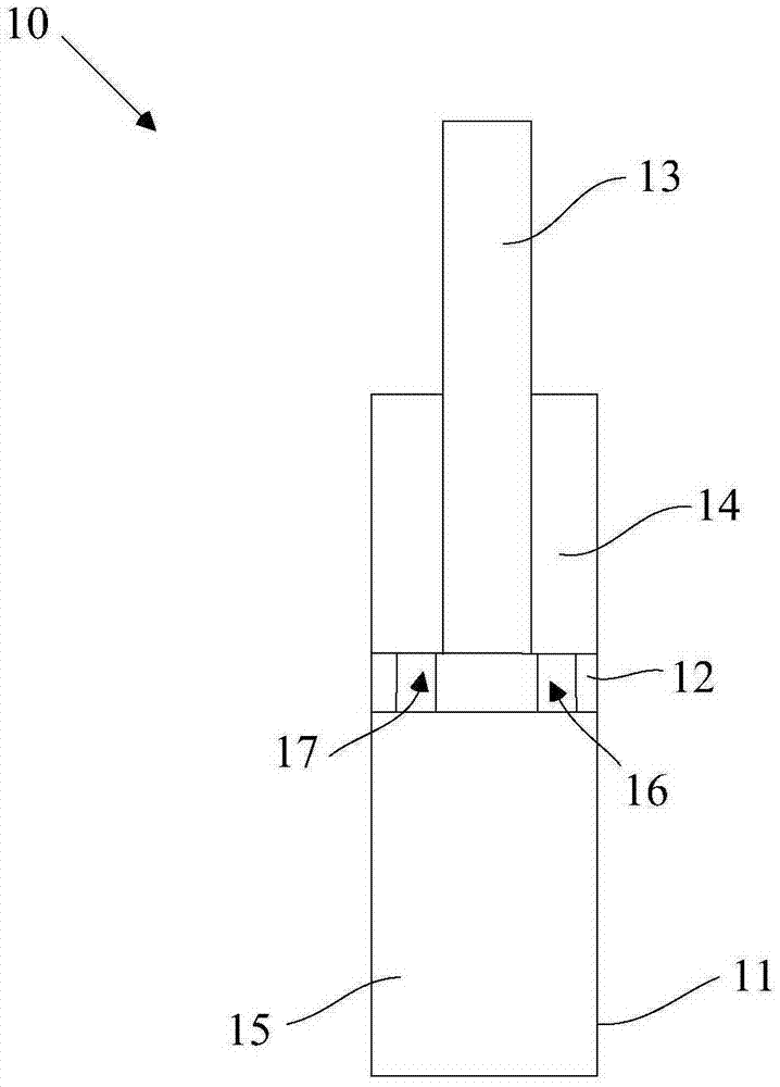
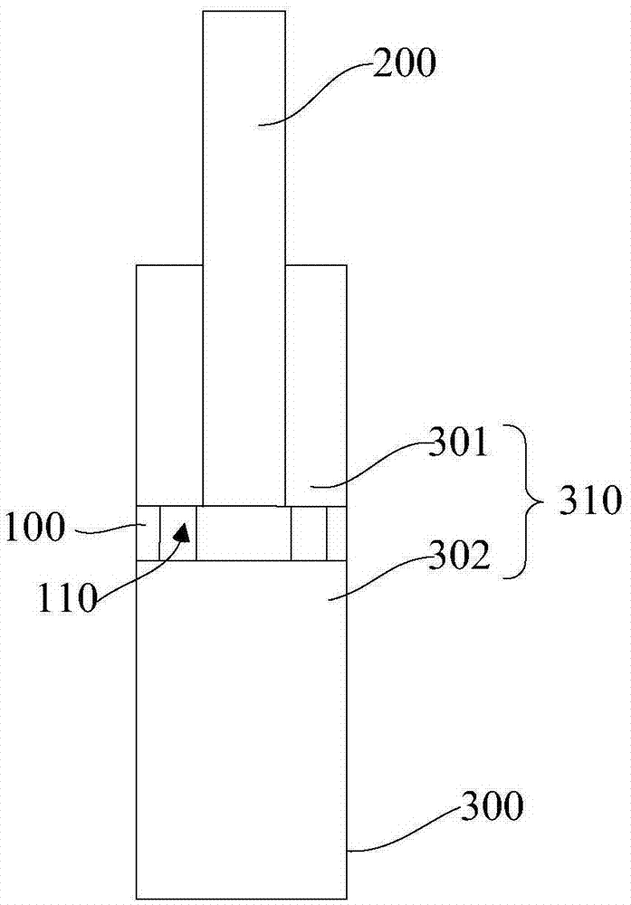
[0121] refer to image 3 and combine Figure 4 As shown, the embodiment of the present invention provides an electrorheological fluid shock absorber, including: a piston 100, and a piston rod 200 arranged on the piston 100, the piston rod 200 is installed on the piston 100 through a lock nut 101; a working chamber 310 , the piston 100 is located in the working chamber 310. In this embodiment, the working chamber 310 is sleeved on the outer peripheral surface of the piston 100; a piston rubber 102 is provided between the outer peripheral surface of the piston 100 and the working chamber 310, and the piston rubber 102 adopts Adding a high-performance filler modified filled polytetrafluoroethylene material can make the outer peripheral surface of the piston 100 and the inner peripheral surface of the working chamber 310 tightly sealed. At the same time, when the piston 100 moves axially in the working chamber 310, the piston wraps The rubber 102 is wear-resistant, and the fricti...

Embodiment 2

[0127] In this embodiment, the structure of the working chamber 310 is the same as that of the working chamber 310 in Embodiment 1, the difference is that, refer to Figure 4 , also includes: a closed first annular chamber 601 surrounding the upper and lower working chambers; a ring member 602 is arranged in the first annular chamber 601, and the ring member 602 divides the first annular chamber 601 into an upper chamber 601a and a lower chamber 601b, the ring 602 can move under the pressure difference between the upper working chamber 301 and the lower working chamber 302; the upper chamber 601a is filled with giant electrorheological fluid, and the lower chamber 601b is filled with compressed air; the compressed air is an inert gas , such as nitrogen, the air pressure is 1Mpa-1.2Mpa, including 1Mpa and 1.2Mpa; the ring 602 can be a ring with a certain thickness, and the ring 602 is closely attached to the inner peripheral surface of the ring cavity 601; the upper cavity 601a ...

Embodiment 3

[0140] In this embodiment, the structure of the working chamber 310 is the same as that of the working chamber 310 in Embodiment 1, the difference is that, refer to Figure 9 , in this embodiment, it also includes: a closed second annular chamber 701 surrounding the upper and lower working chambers; the second annular chamber 701 communicates with the upper working chamber 301 and the lower working chamber 302 respectively, and the second annular chamber 701 serves as a damping channel .

[0141] Also includes: a valve cover 400, the top wall of the upper working chamber 301 and the second annular cavity 701 is served by the valve cover 400; the valve cover 400 has an annular gap 401 around the piston rod 200, and the annular gap 401 communicates with the second annular cavity 701 and The upper working chamber 301 ; or, the side wall of the second annular chamber 701 has a hole, and the hole communicates the second annular chamber 701 with the upper working chamber 301 .

[0...


PUM

PropertyMeasurementUnit
Damping forceaaaaaaaaaa

Abstract

The invention discloses an electrorheological fluid shock absorber and a control method, control unit and ECU thereof and an automobile. The electrorheological fluid shock absorber comprises pistons, a piston rod arranged on the pistons, a working cavity, giant electrorheological fluids and damping channels. The pistons divide the working cavity into an upper working cavity body and a lower working cavity body which are filled with the giant electrorheological fluids. The damping channels communicate with the upper working cavity body and the lower working cavity body correspondingly. The giant electrorheological fluids can flow through the damping channels from the upper working cavity body and then flow to the lower working cavity body, or the giant electrorheological fluids can flow through the damping channels from the lower working cavity body and then flow to the upper working cavity body. The damping channels are connected with a power source through wires. According to the electrorheological fluid shock absorber, a large damping force debugging range under relatively low voltage can be obtained; damping force changing along with the change of the voltage is in short-sighted linear change, so that control is convenient; and meanwhile the requirement for gaps of the damping channels is low, and the electrorheological fluid shock absorber is not liable to penetrate and block.

Description

technical field [0001] The invention relates to the technical field of automobiles, in particular to an electrorheological fluid shock absorber, a control method thereof, a control unit, an ECU and an automobile. Background technique [0002] The performance of the shock absorber in the traditional automobile suspension system is not adjustable, especially the damping force of the shock absorber is not adjustable. Its main disadvantage is that the damping force provided by the shock absorber is only ideal for a certain working condition, and the ideal damping effect cannot be achieved for working conditions far away from the specified working conditions. Obviously, the most ideal is the so-called active or semi-active suspension system. At this time, the damping performance of its shock absorber can be adjusted and controlled in real time, that is, it can adjust the damping force of the shock absorber according to different road conditions. Buffer the impact force transmitt...

Claims


Application Information

Patent Timeline
IPC IPC(8): F16F9/53F16F9/32
CPCF16F9/3207F16F9/532
Inventor 段绪伟王宇飞戴益亮谢涛王申旭杜滢君
Owner SAIC MOTOR
Why Eureka
Try Eureka