Optical fiber displacement sensing system-based displacement measurement signal analysis method

A signal analysis method and displacement sensing system technology, applied in the field of sensors, can solve problems such as environmental adaptability and low stability, and achieve the effects of improving test sensitivity, improving stability, and reducing interference

Active Publication Date: 2017-06-30
为度科创检测技术(苏州)有限公司
View PDF5 Cites 9 Cited by
  • Summary
  • Abstract
  • Description
  • Claims
  • Application Information

AI Technical Summary

Problems solved by technology

[0004] The technical problem to be solved by the present invention is that there are technical problems of low environmental adaptability and low stability in the prior art

Method used


Image

  • Optical fiber displacement sensing system-based displacement measurement signal analysis method
  • Optical fiber displacement sensing system-based displacement measurement signal analysis method
  • Optical fiber displacement sensing system-based displacement measurement signal analysis method

Examples


Embodiment 1

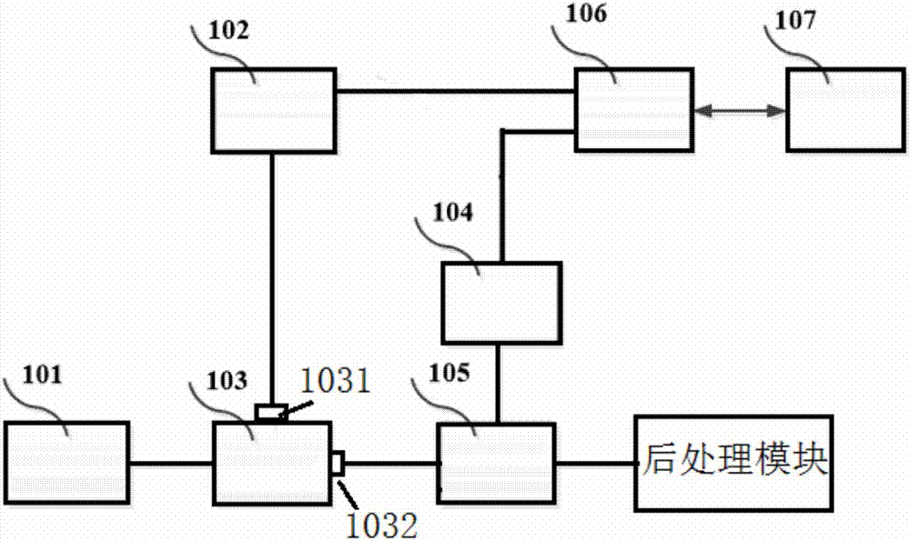
[0040] Such as figure 1, the present embodiment provides an optical fiber displacement sensing system, the optical fiber displacement system includes a signal source 101, an object to be measured, and a power divider connected to the signal source 101; the power divider 103 The first output end is connected to the direct modulation laser 102; the direct modulation laser 102 is connected to the optical fiber displacement sensing probe 106; the optical fiber displacement sensing probe 106 is connected to the high-speed photodetector 104; the IQ mixer 105 radio frequency input With the high-speed photodetector 104, the input end of the local oscillator is connected to the second output end of the power divider, and the output end is connected to the post-processing module in turn; the signal source 101 is used to output microwave signals, and the microwave signals are passed through the second class After distribution by the power divider 103, it is modulated into an optical carr...

Embodiment 2

[0050] This embodiment further improves the post-processing module on the basis of Embodiment 1, which can further reduce the interference of external factors on the optical fiber displacement sensing system.

[0051] Described post-processing module also comprises filter 108, and described filter 108 is connected to mixer output terminal and signal amplifier 109; Described filter 108 passband frequency range comprises mixer output terminal operating frequency, and described filter 108 is used to eliminate interference signals. The filter 108 is a low-pass filter, and the cut-off frequency of the low-pass filter is greater than the working frequency of the output terminal of the mixer.

[0052] The interference signal outside the working frequency of the mixer can be filtered out by the filter, which can further reduce the interference, especially the interference of environmental factors. The stability and sensitivity of the optical fiber displacement sensing system in this ...


PUM


Abstract

The present invention relates to an optical fiber displacement sensing system-based displacement measurement signal analysis method. The main objective of the invention is to solve the technical problems of poor environmental adaptability, serious influence of environmental factors and poor stability in the prior art. According to the method of the invention, a signal source, an object to be measured and a bisector power divider connected with the signal source are adopted; the first output end of the bisector power divider is connected with a directly modulated laser; the directly modulated laser is connected with an optical fiber displacement sensing probe; the optical fiber displacement sensing probe is connected with a high-speed photoelectric detector; the radio frequency input end of an IQ mixer is connected with the high-speed photoelectric detector; the local oscillation input end of the IQ mixer is connected with the second output end of the bisector power divider; the output end of the IQ mixer is connected with a post-processing module; the signal source is used for outputting microwave signals; the microwave signals pass through the bisector power divider and then are converted into optical carrier signals by the directly modulated laser; and the high-speed photoelectric detector is used for converting the optical wave signals into microwave signals. With the method provided by the technical schemes of the invention adopted, problems can be well solved. The method can be applied to the optical fiber displacement sensor industry production.

Description

technical field [0001] The invention relates to the sensor field, can be used in the communication field and medical equipment, and particularly relates to a displacement measurement signal analysis method based on an optical fiber displacement sensing system. Background technique [0002] Sensors are developing towards sensitivity, precision, adaptability, compactness and intelligence. In this process, fiber optic sensors, a new member of the sensor family, are favored. Optical fiber has many excellent properties, including the performance of anti-electromagnetic and atomic radiation interference, the mechanical properties of thin diameter, soft quality and light weight; the electrical properties of insulation and non-induction; the chemical properties of water resistance, high temperature resistance and corrosion resistance, etc. It can play the role of human eyes and ears in high temperature areas, such as nuclear radiation areas, and can also go beyond human physiologic...

Claims


Application Information

Patent Timeline
Patent Type & Authority Applications(China)
IPC IPC(8): G01B11/02
CPCG01B11/02
Inventor 不公告发明人
Owner 为度科创检测技术(苏州)有限公司
Why Eureka
Try Eureka