Power cable joint and manufacturing method thereof

A power cable and stress cone technology, applied in the field of prefabricated power cable intermediate joints and their production, can solve the problems of inaccurate positions, inability to detect and locate cable joints, and inability to detect discharge conditions at joints, and achieve a simple joint structure. Effect

Active Publication Date: 2017-06-30
GLOBAL ENERGY INTERCONNECTION RES INST EURO GMBH +3
View PDF7 Cites 9 Cited by
  • Summary
  • Abstract
  • Description
  • Claims
  • Application Information

AI Technical Summary

Problems solved by technology

[0005] Therefore, the technical problem to be solved by the present invention is to overcome the inability of the power cable joint temperature measurement system in the prior art to detect the entire cable joint and locate the abnormal point, the discharge situation at the joint cannot be detected, and the position of the power cable joint built-in optical fiber is not accurate. and the defects that are easy to bring in impurities, a power cable intermediate joint and its manufacturing method are provided

Method used


Image

  • Power cable joint and manufacturing method thereof
  • Power cable joint and manufacturing method thereof
  • Power cable joint and manufacturing method thereof

Examples


Embodiment 1

[0039] A power cable joint, comprising:

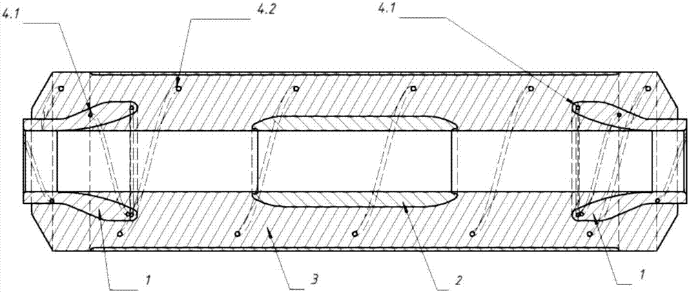
[0040] High voltage shielding tube 2;

[0041] The joint body is wrapped on the outside of the high-voltage shielding tube;

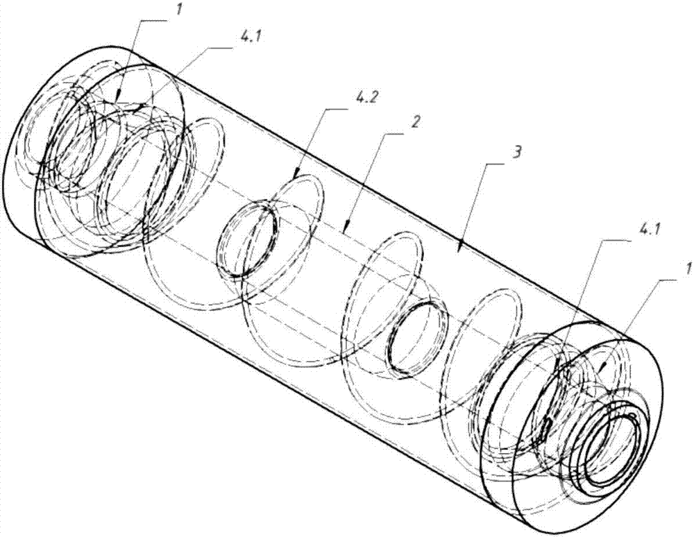
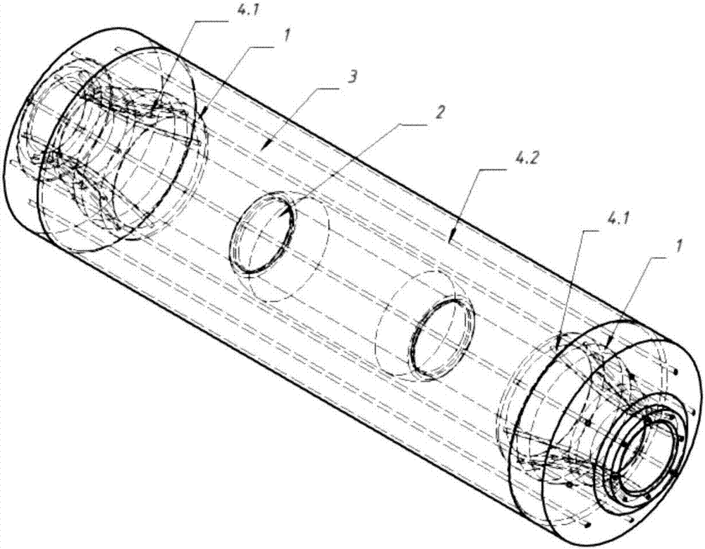
[0042] The optical fiber sensor only includes the optical fiber itself, which is located inside the joint body and runs through the entire joint body; the optical fiber sensor has a certain distance from the edge of the joint body, and the optical fiber sensor is connected to the temperature detection system and the discharge detection system.

[0043] In the present invention, the optical fiber sensor is arranged inside the joint body and runs through the entire joint body. At the same time, there is a certain distance between the optical fiber and the edge of the joint body, which simplifies the structure of the joint. The discharge phenomenon interferes with the detection of the electric field strength, so that the discharge situation at the joint body can be detected more accurately.

[0044] The joint bod...

Embodiment 2

[0049] The difference between this embodiment and Embodiment 1 is that: the optical fiber sensor is disposed inside the connector body in a straight-through manner. Others are consistent with Example 1.

Embodiment 3

[0051] The method for making the above-mentioned power cable connector includes the following steps:

[0052] Include the following steps:

[0053] Step 1: Through electric field strength analysis and thermal analysis, determine the best fiber optic sensor implantation position inside the connector body; import this design into the mold design, and manufacture the corresponding connector body mold;

[0054] Step 2: Preset the optical fiber sensor in the mold of the joint body in a helical winding and / or straight-through manner on the workbench at the optimal implantation position of the optical fiber sensor, and then form the joint body by conventional injection molding methods;

[0055] Step 3: Sleeve the connector body on the outside of the high voltage shielding tube to form the power cable connector.

[0056] The joint body includes a stress cone 1 and an electric field enhancing insulator 3; the optical fiber sensor includes a first optical fiber 4.1 and a second optical...


PUM


Abstract

The invention provides a power cable joint, characterized by comprising: a high voltage shielded tube, a joint body wrapped on the outer side of the high voltage shielded tube, and an optical fiber sensor containing only the optical fiber itself and arranged inside the joint body in a way of penetrating the entire joint body. The optical fiber sensor is some distance away from the edges of the joint body. The optical fiber sensor is connected with a temperature detection system and a power discharge detection system. According to the invention, the structure of the joint detection system is simplified and no area is free of detection. At the same time, the interference of the power discharging phenomenon at the intersecting part to the electric field strength detection can be prevented so as to accurately detect the power discharging condition at the joint body position.

Description

technical field [0001] The invention belongs to the field of power cable accessories, and in particular relates to a prefabricated power cable intermediate joint with built-in optical fiber and a manufacturing method thereof. Background technique [0002] The intermediate joint body of ordinary medium and high voltage power cables does not contain built-in optical fiber. Although the function only realizes the optimization of the electric field, the supporting temperature detection and partial discharge early warning system cannot carry out early warning and monitoring on the existing intermediate joint body, resulting in the failure of the entire cable. The system forms a monitoring blind zone at the intermediate joint. [0003] In order to facilitate early warning of the power cable intermediate joint body, a new type of power cable joint has appeared in the prior art, such as Chinese patent CN104977097A, which fixes a temperature measuring probe 8 on the cable joint, and ...

Claims


Application Information

Patent Timeline
Patent Type & Authority Applications(China)
IPC IPC(8): H02G15/18G01R31/12G01K11/32
CPCH02G15/18G01K11/32G01R31/1218
Inventor 周明瑜雷宪章贺之渊韩正一王海田蔡力钧刘伟麟蓝元良孟晓刚李多
Owner GLOBAL ENERGY INTERCONNECTION RES INST EURO GMBH
Why Eureka
Try Eureka