Absorption-reactivator for continuously trapping carbon dioxide in flue gas

A carbon dioxide and regenerator technology, applied in the direction of direct carbon dioxide emission reduction, filter regeneration, combustible gas purification, etc.

Active Publication Date: 2017-07-04
长沙紫宸科技开发有限公司
View PDF5 Cites 5 Cited by
  • Summary
  • Abstract
  • Description
  • Claims
  • Application Information

AI Technical Summary

Problems solved by technology

This method has relative advantages in cost, but the process and system equipment are still relatively complicated, requiring high pressure, low temperature and long reaction time, and cannot run continuously
[0008] In the field of cement production worldwide, although there is emphasis on the low-carbon emission reduction of cement enterprises, because it is more difficult to deal with post-combustion flue gas, no specific carbon dioxide capture, sealing and application of cement plant flue gas has been seen so far. research or practice report

Method used


Image

  • Absorption-reactivator for continuously trapping carbon dioxide in flue gas
  • Absorption-reactivator for continuously trapping carbon dioxide in flue gas
  • Absorption-reactivator for continuously trapping carbon dioxide in flue gas

Examples


Embodiment 1

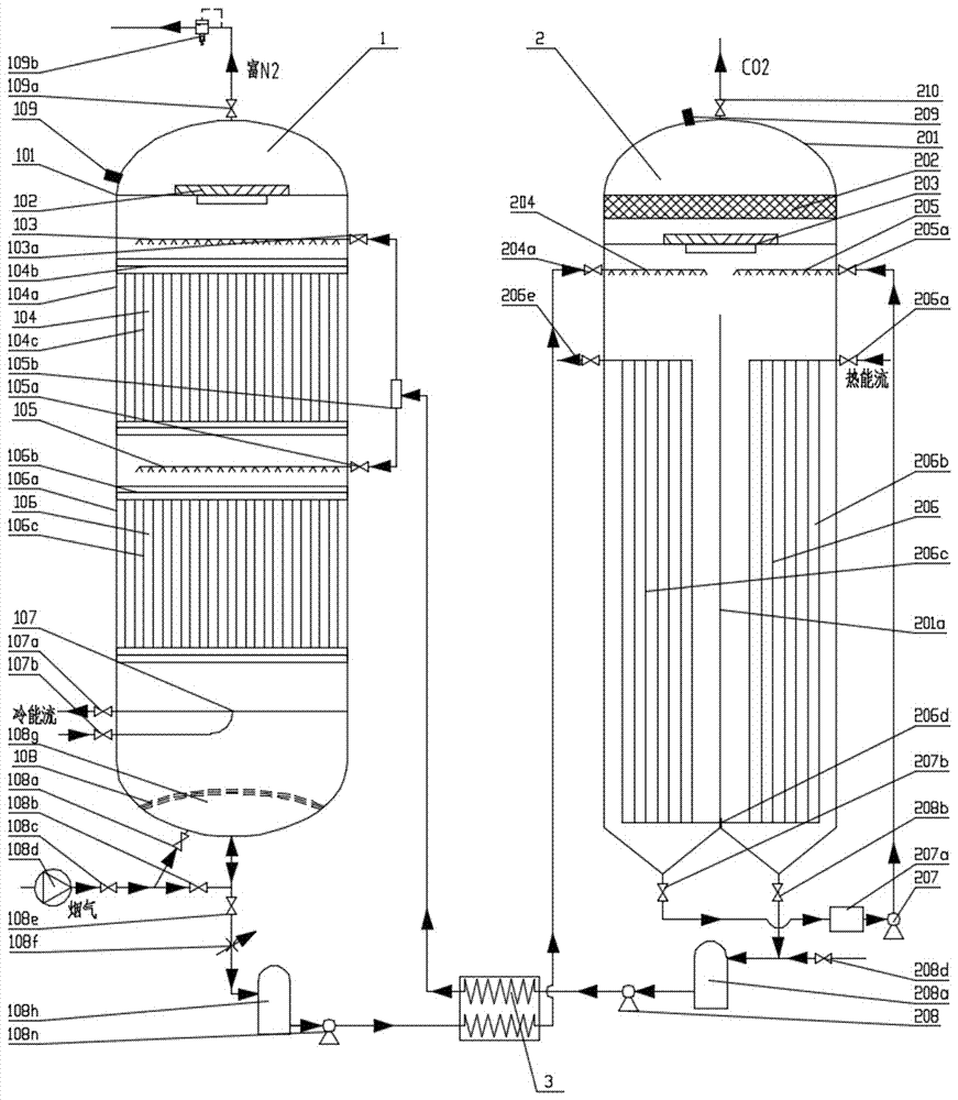
[0067] refer to figure 1 , figure 2 and image 3 , an absorber-regenerator adapted to continuously capture CO2 in flue gas, including flue gas CO 2 Continuous absorption regeneration unit, flue gas CO 2 The continuous absorption regeneration unit consists of continuous CO 2 Absorption tower 1, continuous CO 2 The regeneration tower 2 and the cold / heat exchange device 3 are connected in series, and the continuous CO 2 Absorber and Continuous CO 2 The regeneration towers are connected through the cold / heat exchange device 3 .

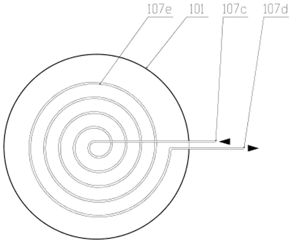
[0068] The continuous CO 2 The absorption tower 1 includes a shell 101, and the shell 101 is provided with a gas-liquid separation device 102, at least one atomizing liquid spraying device, at least one wire mesh capture bed device, a cooling device 107, and a gas inlet and distribution device in order from top to bottom. CO with drain 108 2 Hydrate storage chamber 108g.

[0069] In this embodiment, the number of stages of the atomizing liquid ...

Embodiment 2

[0083] The difference between this embodiment and embodiment 1 is:

[0084] refer to Figure 4 , the number of stages of the atomizing liquid spraying device and the number of stages of the wire mesh trapping bed device are one level, that is, the first stage atomizing liquid spraying device 103, the first stage wire mesh trapping bed device 104, the first stage atomizing spraying device The liquid device 103 is arranged above the first-stage wire mesh capture bed device 104 .

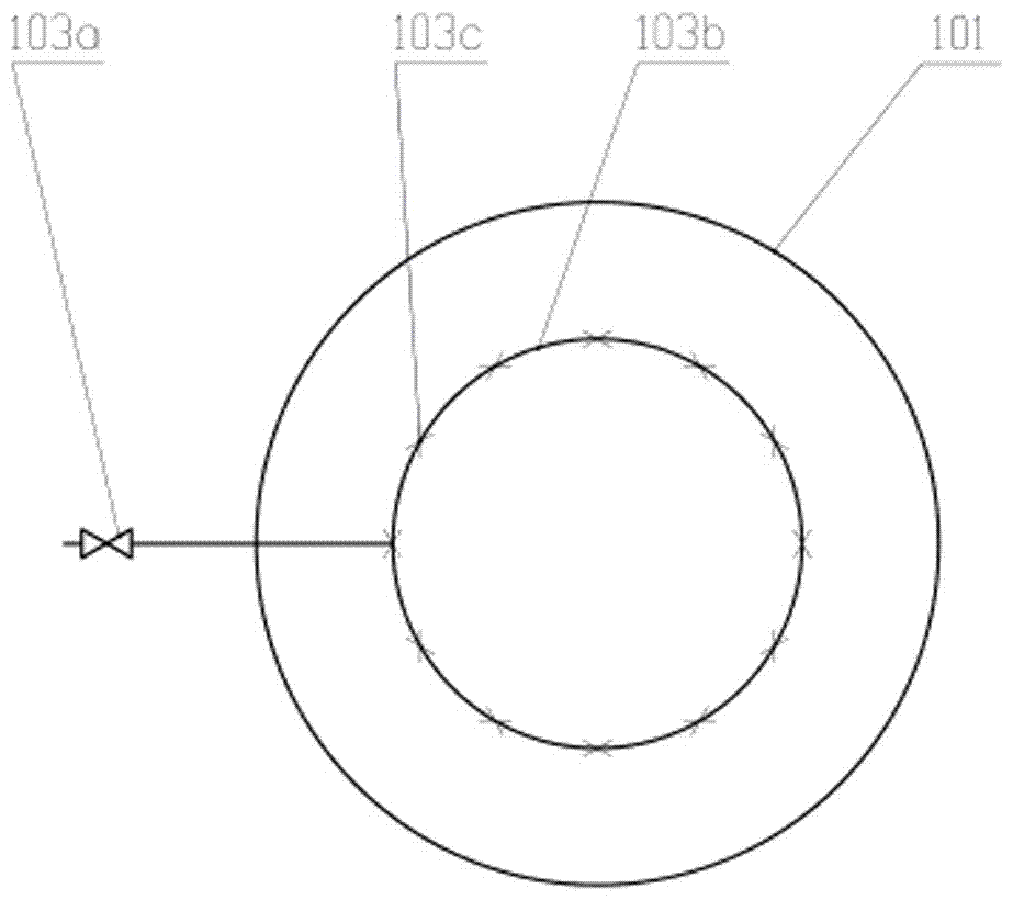
[0085] The casing 101 is provided with a trapping agent inlet pipe, the inlet end of the trapping agent liquid inlet pipe is connected to the cold / heat exchange device 3, and the outlet end of the collector agent liquid inlet pipe is provided with a seventh pipe valve 103a. The inlet end of the stage atomizing liquid spraying device is connected with the outlet end of the collecting agent inlet pipe.

[0086] All the other are with embodiment 1.

Embodiment 3

[0088] The difference between this embodiment and embodiment 1 is:

[0089] refer to Figure 5 , the number of stages of the atomizing liquid spraying device and the number of stages of the wire mesh trapping bed device are one level, that is, the first stage atomizing liquid spraying device 103, the first stage wire mesh trapping bed device 104, the first stage atomizing spraying device The liquid device 103 is arranged above the first-stage wire mesh capture bed device 104 .

[0090] The casing 101 is provided with a trapping agent inlet pipe, the inlet end of the trapping agent liquid inlet pipe is connected to the cold / heat exchange device 3, and the outlet end of the collector agent liquid inlet pipe is provided with a seventh pipe valve 103a. The inlet end of the stage atomizing liquid spraying device is connected with the outlet end of the collecting agent inlet pipe.

[0091] The heating device 206 only includes a first-stage decarburization device, that is, a first-...


PUM


Abstract

The invention relates to an absorption-reactivator for continuously trapping carbon dioxide in flue gas. The absorption-reactivator comprises a flue gas CO2 continuous absorption regeneration unit, the flue gas CO2 continuous absorption regeneration unit is formed by a continuous CO2 absorbing tower, a continuous CO2 regeneration tower, a cold / heat exchange device which are connected in series; and the continuous CO2 absorbing tower and the continuous regeneration tower are communicated through the cold / heat exchange device. The absorption-reactivator breakthroughs the equipment technical bottleneck of traditional trapping of CO2 in industrial flue gas, especially that a secondary pollution-free hydrate method for trapping CO2 is difficult to adapt the large-flow continuous trapping, and the invention creatively develops the apparatus for continuously trapping carbon dioxide in flue gas by the hydrate method, the apparatus has the advantages of novel and simple structure as well as easy control, and creates the equipment condition for large-scale continuous trapping of CO2 by a post-combustion method, and especially creates the equipment condition of large-scale continuous trapping of industrial flue gas CO2 by solvent-free or auxiliary agent secondary pollution.

Description

technical field [0001] The invention relates to the technical field of environmental protection equipment, in particular to a CO 2 The capture method adopts the hydrate method to continuously capture the carbon dioxide in the flue gas absorption-regenerator. Background technique [0002] Climate change has become one of the issues affecting human survival and development, and industrial emissions of carbon dioxide are considered to be the main cause of climate warming. my country, as the largest developing country in the world, uses coal as its primary energy and fire The secondary energy structure dominated by power generation, with the rapid growth of economic aggregate, the CO of primary energy and secondary energy 2 Emissions are characterized by rapid growth and large volumes. However, the high investment and high capture cost of the current CCS or CCUS technology for carbon emission reduction and climate change have become serious obstacles to the promotion and applic...

Claims


Application Information

Patent Timeline
Patent Type & Authority Applications(China)
IPC IPC(8): B01D53/14B01D53/18B01J20/34F27D17/00
CPCB01D53/14B01D53/1475B01D53/18B01D53/185F27D17/00B01D2258/0283B01D2257/504Y02P10/122
Inventor 尹小林
Owner 长沙紫宸科技开发有限公司
Why Eureka
Try Eureka