Obstructive piston type particle damper

A particle damper and particle damping technology, applied in shock absorbers, shock absorbers, friction shock absorbers, etc., can solve the problems of small contact area between piston rod and particles, difficult to control the size of damping, affecting engineering applications, etc. To achieve the effect of simple and reliable structure, low cost and stable vibration reduction effect

Active Publication Date: 2017-07-04
WUHAN UNIV OF SCI & TECH
View PDF6 Cites 4 Cited by
  • Summary
  • Abstract
  • Description
  • Claims
  • Application Information

AI Technical Summary

Problems solved by technology

[0003] Piston-type particle damper, such as "a piston-type particle damper" (CN103266679A) patented technology, although this technology has its advantages, it still has a small damping And the defect that the size of the damping is not easy to control affects its engineering application
Another example is the patented technology of "a solid particle damper device" (CN104632990A). When the piston rod moves, the volume of the volume chamber will change, and the damping force will be unstable; the contact area between the piston rod and the particles is small, and the damping cannot be changed and controlled. The size of the damping force

Method used


Image

  • Obstructive piston type particle damper
  • Obstructive piston type particle damper
  • Obstructive piston type particle damper

Examples


Embodiment 1

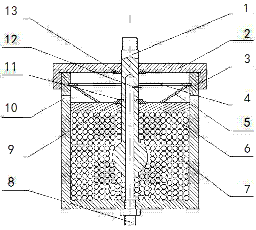
[0026] An obstructive piston type particle damper. The obstructive piston type particle damper such as figure 1 As shown, it includes a damper housing 3 , a granular damping material 7 , a cover plate 6 , a belleville spring 5 , a piston rod 1 , a guide rod 8 and a damper cover 2 .

[0027] like figure 1 As shown, the damper housing 3 is a hollow cylinder with one end closed, a screw hole is provided at the center of the closed end, and an external thread is provided at the open end of the hollow cylinder, and the housing next to the external thread is Two first ventilation holes 10 are provided. An inner annular groove is provided close to the inner wall of the port, and the distance between the inner annular groove and the bottom of the damper housing 3 is 90-93% of the height of the damper housing 3 .

[0028] like figure 1 As shown, the port of the damper housing 3 is fixedly connected with the damper cover 2 through threads, and an inner snap ring 4 is installed in th...

Embodiment 2

[0036] An obstructive piston type particle damper. Except following, all the other are with embodiment 1:

[0037] The distance between the inner annular groove and the bottom of the damper housing 3 is 92% to 94% of the height of the damper housing 3; the distance between the cover plate 6 and the bottom of the damper housing 3 is 73% of the height of the damper housing 3 ~78%; the distance between the lower end of the piston rod 1 and the bottom of the damper housing 3 is 23-28% of the height of the damper housing 3; the hole depth of the circular hole is 73-78% of the length of the piston rod 1 ; The diameter of the sphere is 1-4mm.

[0038] The particle damping material 7 is made of lead.

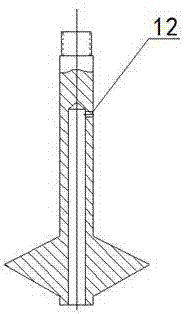
[0039] like figure 2 As shown, the body of revolution is rhombohedral.

Embodiment 3

[0041] An obstructive piston type particle damper. Except following, all the other are with embodiment 1:

[0042] The distance between the inner annular groove and the bottom of the damper housing 3 is 93-95% of the height of the damper housing 3; the distance between the cover plate 6 and the bottom of the damper housing 3 is 75% of the height of the damper housing 3 ~80%; the distance between the lower end of the piston rod 1 and the bottom of the damper housing 3 is 25-30% of the height of the damper housing 3; the hole depth of the circular hole is 75-80% of the length of the piston rod 1 ; The diameter of the sphere is 2-5mm.

[0043] The granular damping material 7 is made of copper or aluminum.

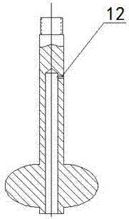
[0044] like image 3 As shown, the body of revolution is an ellipsoid.

[0045] Compared with the existing technical solutions, this specific embodiment has the following positive effects:

[0046] In this specific embodiment, the particle damping material 7 fills the c...


PUM


Abstract

The invention relates to an obstructive piston type particle damper. According to the technical scheme, the lower portion of a guide rod (8) is fixedly connected with a screw hole in the closed end of a damper shell (3) through a thread, and the lower end of the guide rod (8) is fixedly connected with a base through a thread. The upper end of a piston rod (1) penetrate a cover plate (6) and a damper cover (2) to be connected with an external mechanical vibrating system, and the upper portion of the guide rod (8) is movably sleeved with the lower portion of the piston rod (1). A cavity below the cover plate (6) is filled with particle damping materials (7). The piston rod (1) is a whole formed by a rod body and a rotary body, and the rotary body is a sphere or a spheroid or a rhombohedron. A round hole is formed in the lower end face of the piston rod (1) inwards along the axis, and the diameter of the round hole and the guide rod (8) are in clearance fit. The obstructive piston type particle damper is simple and reliable in structure, convenient to manufacture, low in cost, stable in damping effect and wide in application range, can generate large damping and adjust the magnitude of the damping, is suitable for vibration attenuation of periodic vibrating equipment, and is also suitable for vibration attenuation of impact vibrating equipment.

Description

technical field [0001] The invention belongs to the technical field of piston type particle dampers. In particular, it relates to an obstructive piston-type particle damper. Background technique [0002] Particle damping is to fill metal or non-metallic particles into a cavity structure according to a certain filling ratio, and consume the kinetic energy of the system through the collision, friction and momentum exchange between particles and between particles and the inner wall of the cavity, so as to achieve the reduction vibration purpose. According to the difference between the number of damping units and the number of particles in the damping unit, traditional particle dampers can be divided into four categories, namely, single-unit single-particle impact dampers, multiple-unit single-particle impact dampers, and single-unit impact dampers. Multi-particulate damper for one unit (or non-obstructive particulate damper) and multi-particulate damper for multiple units. W...

Claims


Application Information

Patent Timeline
Patent Type & Authority Applications(China)
IPC IPC(8): F16F7/01
CPCF16F7/015
Inventor 杨啟梁胡溧
Owner WUHAN UNIV OF SCI & TECH
Why Eureka
Try Eureka