
Control device for internal combustion engines

A technology for control devices and internal combustion engines, which is applied in engine control, fuel injection control, electrical control, etc., and can solve the problems of dividing the number of times that fuel injection cannot be divided into multiple times, reducing the proportion of the amount that cannot be injected, and increasing the number of discharged exhaust gas particles, etc.

Inactive Publication Date: 2017-07-04
NISSAN MOTOR CO LTD
View PDF8 Cites 1 Cited by
  • Summary
  • Abstract
  • Description
  • Claims
  • Application Information

AI Technical Summary

Problems solved by technology

[0004] However, in this patent document 1, if the engine load when resuming fuel injection from the fuel-cut state is low and the fuel injection amount in one combustion cycle becomes small, there is a possibility that the minimum fuel injection pulse width of the fuel injection valve is restricted. It may not be possible to divide the number of fuel injections in one combustion cycle into multiples, and it may not be possible to reduce the ratio of the first injection amount in the divided injection
Therefore, in Patent Document 1, when resuming fuel injection from the fuel-cut state, depending on the situation, the amount of exhaust gas particles and the number of exhaust gas particles may increase.

Method used


Image

  • Control device for internal combustion engines
  • Control device for internal combustion engines
  • Control device for internal combustion engines

Examples


Embodiment Construction

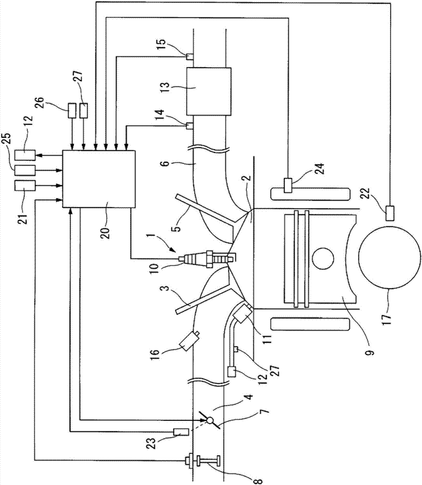
[0020] Hereinafter, an embodiment of the present invention will be described in detail based on the drawings. figure 1 The schematic structure of the internal combustion engine 1 to which the present invention is applied is shown. Among them, the internal combustion engine 1 uses gasoline as fuel, for example.

[0021] In the combustion chamber 2 of the internal combustion engine 1, an intake passage 4 is connected via an intake valve 3, and an exhaust passage 6 is connected via an exhaust valve 5.

[0022] An electronically controlled throttle valve 7 is arranged in the intake passage 4. An air flow meter 8 that detects the amount of intake air is provided on the upstream side of the throttle valve 7. The detection signal of the air flow meter 8 is input to an ECU (Engine Control Unit) 20.

[0023] At the top of the combustion chamber 2, a spark plug 10 is arranged so as to face the piston 9. A first fuel injection valve 11 that directly injects fuel into the combustion chamber 2...


PUM


Abstract

A control device for internal combustion engines, having: a first fuel injection valve that injects fuel directly into a combustion chamber; and a pressure regulator capable of changing the fuel pressure supplied to the first fuel injection valve. When prescribed fuel cut conditions are met, a fuel cut is implemented whereby fuel injection by the first fuel injection valve is stopped. When prescribed fuel cut recovery conditions are met during fuel cut, fuel injection by the first fuel injection valve is recommenced. When fuel injection is recommenced after fuel cut, the fuel pressure supplied to the first fuel injection valve is set higher than the normal fuel pressure determined in accordance with the driving state. As a result, spray atomization and vaporization are promoted and the exhaust particle discharge amount and the number of discharged exhaust particles can be suppressed, when recommencing fuel injection after fuel cut has ended.

Description

Technical field [0001] The invention relates to a control device for an internal combustion engine that directly injects fuel into a combustion chamber. Background technique [0002] Currently, a direct-injection internal combustion engine is known in which fuel is injected into the combustion chamber multiple times in a single combustion cycle to reduce the amount of fuel injected each time and reduce the adhesion of fuel to wall surfaces. [0003] For example, Patent Document 1 discloses a technique that, when restarting the fuel injection from a fuel cut state in which the fuel injection into the combustion chamber is temporarily stopped, the fuel injection into the combustion chamber is stopped for a time The longer the length, the smaller the ratio of the initial injection amount in the split injection, and the more the emission amount of exhaust particulates is suppressed. [0004] However, in this Patent Document 1, if the engine load when restarting fuel injection from the f...

Claims


Application Information

Patent Timeline
Patent Type & Authority Applications(China)
IPC IPC(8): F02D41/04F02D41/02F02D41/12F02D45/00F02D29/02
CPCF02D29/02F02D41/0295F02D41/047F02D41/3836F02D35/025F02D2200/0602F02D41/126F02D41/04F02D41/40F02D2041/389
Inventor 吉村太内田亮伊达知善神尾李奈
Owner NISSAN MOTOR CO LTD
Learn More