Air inducing heat radiation device of wind driven generator cabin

A technology for wind turbines and heat sinks, applied in wind turbines, wind energy power generation, engines, etc., can solve the problems of poor cooling effect and low heat dissipation efficiency, and achieve the effects of avoiding dead zones, saving costs, and improving flow.

Pending Publication Date: 2017-07-07
ZHEJIANG WINDEY
View PDF5 Cites 4 Cited by
  • Summary
  • Abstract
  • Description
  • Claims
  • Application Information

AI Technical Summary

Problems solved by technology

[0004] In order to overcome the deficiencies of low heat dissipation efficiency and poor cooling effect of the existing wind turbine cabin heat dissipation method, the present invention provides a wind turbine cabin induced air cooling device with high heat dissipation efficiency and good cooling effect

Method used


Image

  • Air inducing heat radiation device of wind driven generator cabin
  • Air inducing heat radiation device of wind driven generator cabin
  • Air inducing heat radiation device of wind driven generator cabin

Examples


Embodiment Construction

[0019] The present invention will be further described below in conjunction with the accompanying drawings.

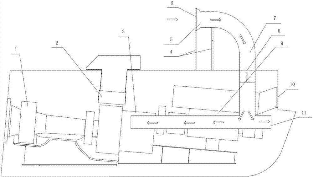
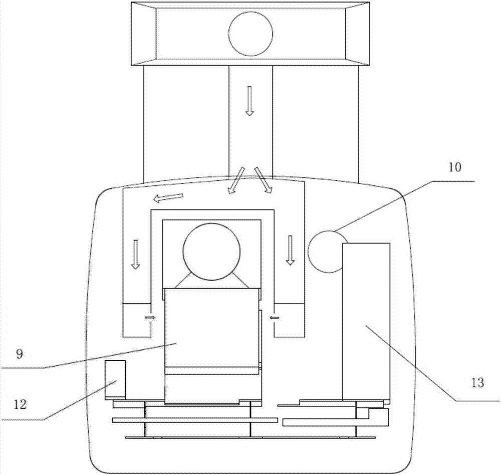
[0020] refer to figure 1 and figure 2 , a kind of air-inducing heat dissipation device for a wind turbine cabin, comprising an air collecting pipe 5, an external air inlet pipeline 7, an air flow regulating valve 8 and an internal ventilation pipeline 11, the air collecting pipe 5 and the external air inlet pipeline 7 Connected, the air collecting pipe 5 and the external air intake pipeline 7 are fixed on the cabin shell through the bracket 4, and an opening is provided in the rear half of the cabin shell, and the external air intake pipeline 7 passes through the opening of the cabin shell and the inside The ventilation pipeline 11 is connected, and the air flow regulating valve 8 is set at the opening of the cabin shell where the air outlet 10 is opened.

[0021] Further, the controlled switch of the air flow regulating valve 8 is connected to a heat dissipation co...


PUM


Abstract

An air inducing heat radiation device of a wind driven generator cabin comprises an air collection pipe, an external air inlet pipeline, an air flow adjusting valve and an internal ventilation pipeline. The air collection pipe is connected with the external air inlet pipeline. The air collection pipe and the external air inlet pipeline are fixed to a cabin shell through a support. An opening is formed in the rear half part of the cabin shell, and the external air inlet pipeline penetrates the opening of the cabin shell to be connected with the internal ventilation pipeline. The air flow adjusting valve is arranged at a hole of the cabin shell. An air outlet is formed in the cabin shell. The air inducing heat radiation device of the wind driven generator cabin is high in heat radiation efficiency and good in cooling effect.

Description

technical field [0001] The invention relates to wind power generator technology, in particular to a heat dissipation device which can effectively improve the heat dissipation effect of internal components of the wind power generator. Background technique [0002] According to field feedback, when the temperature is high in summer, many wind farms limit the power of the unit to ensure the normal operation of the unit, and sometimes cause an alarm to shut down the unit due to overheating of the components. The existence of this problem has caused huge economic losses. [0003] The reason for this problem is that there are a large number of heat-generating components in the engine room, including impellers, gearboxes, generators, bearings and various electrical equipment. The heat of these heat-generating components accumulates in the engine room due to design problems and cannot be discharged in time. , leading to higher and higher temperatures in the engine room, which greatl...

Claims


Application Information

Patent Timeline
Patent Type & Authority Applications(China)
IPC IPC(8): F03D80/60F03D80/80
CPCY02E10/72
Inventor 崔明陈成城吴根勇应有王欣
Owner ZHEJIANG WINDEY
Why Eureka
Try Eureka