Reducing series-parallel connection channel plate type pulsating heat pipe

A pulsating heat pipe and parallel technology, applied in the field of heat transfer enhancement, can solve the problems of poor fluidity of the working medium, no lateral communication, and difficulty in eliminating radial temperature differences.

Pending Publication Date: 2017-07-07
CHANGSHA UNIVERSITY OF SCIENCE AND TECHNOLOGY
View PDF10 Cites 2 Cited by
  • Summary
  • Abstract
  • Description
  • Claims
  • Application Information

AI Technical Summary

Problems solved by technology

1. The equivalent diameter of the pulsation channel remains unchanged. In this case, the cold end has a stronger capillary effect and the fluidity of the working medium becomes poor. The working medium is especially prone to blockage when starting and low heating power, resulting in: ①The heat pipe cannot start smoothly , ② Difficulty in the return flow of the working medium and a good cycle cannot be established, resulting in abnormal operation of the heat pipe and a decrease in heat transfer capacity
2. Each pulsating channel is a closed and independent channel, and the working fluid in the channel cannot exchange material between channels according to the difference and change of working conditions, which makes: ①It is difficult to eliminate the radial temperature difference between channels, resulting in uneven temperature uniformity at the hot end Good; ② There is no effective horizontal communication between the channels, which weakens the convective heat transfer capacity in the tube
3. The traditional parallel channel plate pulsating heat pipe is a single-piece heat pipe. Due to the limitation of the heat dissipation area, its heat dissipation capacity cannot be very large, and it is difficult to meet the cooling of high-power components.

Method used


Image

  • Reducing series-parallel connection channel plate type pulsating heat pipe
  • Reducing series-parallel connection channel plate type pulsating heat pipe
  • Reducing series-parallel connection channel plate type pulsating heat pipe

Examples


Embodiment 1

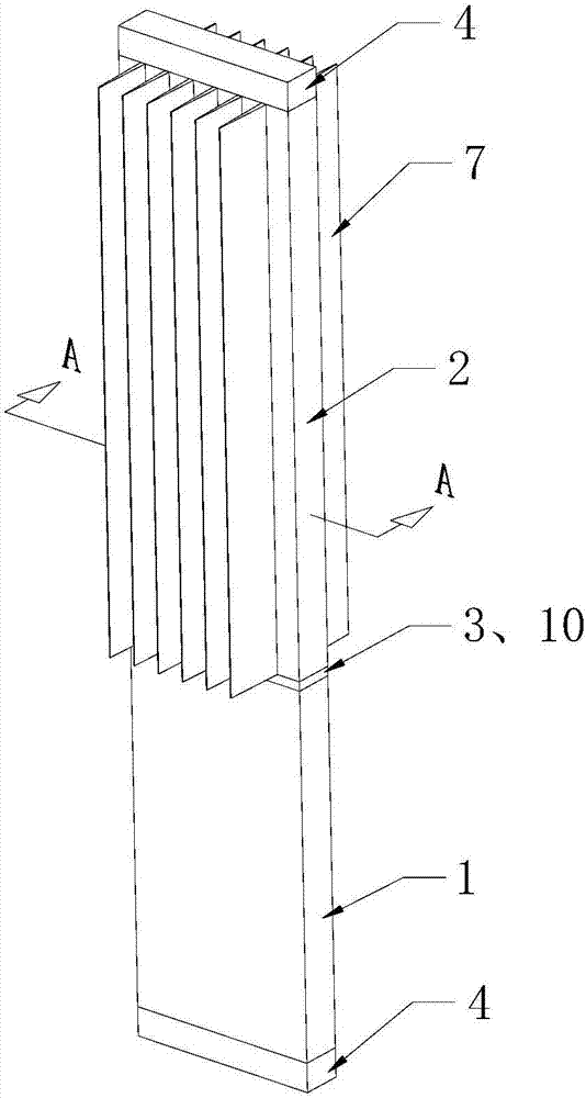
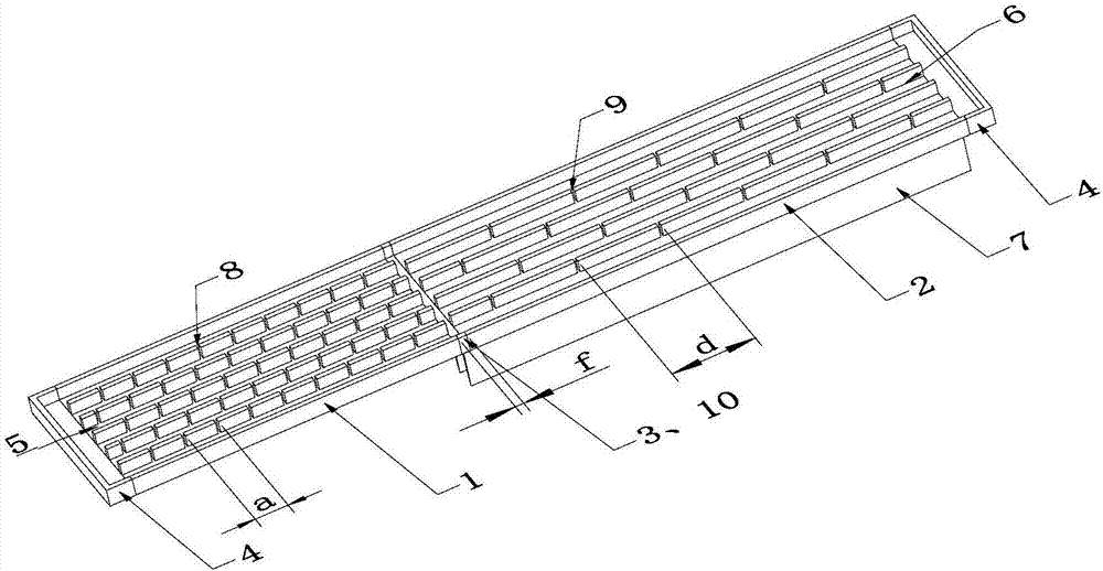
[0050] See attached figure 1 , 2 , 3, 4, 5, 6, the variable-diameter series and parallel channel plate type pulsating heat pipe includes one of the hot ends 1, one of the cold ends 2, and one of the type I intermediates 3, The two heads 4 are characterized in that: the hot end 1 is a rectangular flat plate with uniformly distributed equal-diameter hot-end channels 5 inside; the cold end 2 is a rectangular flat plate with uniformly distributed equal-diameter cold-end channels 6 inside; The equivalent diameter of the channel 6 at the cold end is 2.67 times the equivalent diameter of the channel 5 at the hot end; the hot end 1 and the cold end 2 are connected through the intermediate body 3 .

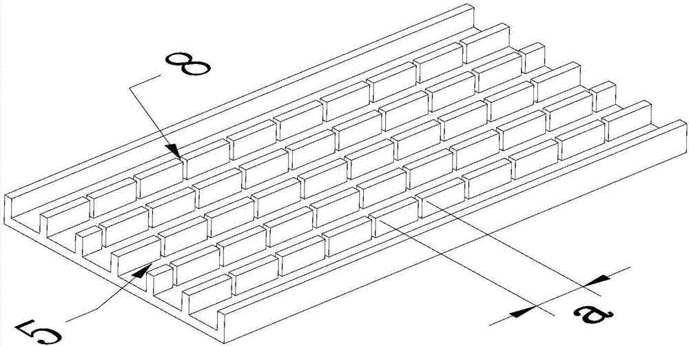
[0051] A balance hole 8 is provided on the partition wall of the adjacent hot end channel 5 in the hot end 1 , and a balance hole 9 is provided on the partition wall of the adjacent cold end channel 6 in the cold end 2 .

[0052] One end of the hot end 1 is connected to the intermediate ...

Embodiment 2

[0068] See attached image 3 , 4 , 6, 7, 8, the variable-diameter series and parallel channel plate type pulsating heat pipes include 1 of the hot ends 1, 2 of the cold ends 2, 1 of the type II intermediates 3, 3 The head 4 is characterized in that: the hot end 1 is a rectangular flat plate with uniformly distributed equal-diameter hot-end channels 5; the cold end 2 is a rectangular flat plate with uniformly distributed equal-diameter cold-end channels 6; The equivalent diameter of the channel 6 at the cold end is 1.67 times the equivalent diameter of the channel 5 at the hot end; the hot end 1 and the cold end 2 are connected through the intermediate body 3 .

[0069] A balance hole 8 is provided on the partition wall of the adjacent hot end channel 5 in the hot end 1 , and a balance hole 9 is provided on the partition wall of the adjacent cold end channel 6 in the cold end 2 .

[0070] One end of the hot end 1 is connected to the intermediate body 3, and the other end is p...

Embodiment 3

[0086] See attached image 3 , 4 , 6, 9, 10, the variable-diameter series, parallel channel plate type pulsating heat pipe includes 1 of the hot end 1, 3 of the cold end 2, 1 of the III-type intermediate 3, 4 The head 4 is characterized in that: the hot end 1 is a rectangular flat plate with uniformly distributed equal-diameter hot-end channels 5; the cold end 2 is a rectangular flat plate with uniformly distributed equal-diameter cold-end channels 6; The equivalent diameter of the channel 6 at the cold end is 1.13 times the equivalent diameter of the channel 5 at the hot end; the hot end 1 and the cold end 2 are connected through the intermediate body 3 .

[0087] A balance hole 8 is provided on the partition wall of the adjacent hot end channel 5 in the hot end 1 , and a balance hole 9 is provided on the partition wall of the adjacent cold end channel 6 in the cold end 2 .

[0088] One end of the hot end 1 is connected to the intermediate body 3, and the other end is provi...


PUM


Abstract

The invention discloses a reducing series-parallel connection channel plate type pulsating heat pipe which comprises a hot end 1, a cold end 2, an intermediate 3 and an end socket 4. The reducing series-parallel connection channel plate type pulsating heat pipe is characterized in that the hot end 1 is a rectangular flat plate with equal-diameter hot end channels 5 evenly distributed inside, the cold end 2 is a rectangular flat plate with equal-diameter cold end channels 6 evenly distributed inside, the equivalent diameter of the cold end channels 6 is 1-10 times that of the hot end channels 5, one end of the hot end 1 is connected with one end of the cold end 2, or the hot end 1 and the cold end 2 are connected through the intermediate 3, and the intermediate 3 is provided with a mixing cavity 10. The reducing series-parallel connection channel plate type pulsating heat pipe is obviously innovated and changed from the structure and the heat transfer mechanism, has actual effects and accords with the physical theory. The cooling principles and requirements of high-heat-flux elements are comprehensively met. The reducing series-parallel connection channel plate type pulsating heat pipe is applied to the high-heat-flux elements to be beneficial to cooling of the elements, and has the positive promoting effect on promoting development of electronic, microelectronic and optoelectronic components and relevant fields.

Description

technical field [0001] The invention discloses a variable-diameter serial and parallel channel plate type pulsating heat pipe, which belongs to the technical field of heat transfer enhancement. [0002] technical background [0003] Today, integrated, efficient, and miniaturized electronic, microelectronic, and optoelectronic components have been widely used in various daily production and living equipment, greatly improving people's production efficiency and quality of life, and the process is endless. However, such devices face the same obstacle in the evolution of integration, high efficiency, and miniaturization—high heat flux density. According to investigations, the current heat flux density of such components is generally close to or exceeds 100W / cm 2 , some even exceed 200W / cm 2 . [0004] High heat flux will generally lead to excessive operating temperature of components. [0005] As we all know, the performance of electronics, microelectronics, and optoelectronic...

Claims


Application Information

Patent Timeline
Patent Type & Authority Applications(China)
IPC IPC(8): F28D15/02
CPCF28D15/02
Inventor 夏侯国伟张俊杰
Owner CHANGSHA UNIVERSITY OF SCIENCE AND TECHNOLOGY
Why Eureka
Try Eureka