A transformer degaussing and verification device

A technology for verifying devices and transformers, which is applied in the direction of instruments, magnetic objects, and the size/direction of magnetic fields, and can solve problems such as poor applicability in production sites, and achieve the effects of light weight, low manufacturing cost, and convenient operation

Active Publication Date: 2019-02-19
SHANGHAI MUNICIPAL ELECTRIC POWER CO
View PDF4 Cites 0 Cited by
  • Summary
  • Abstract
  • Description
  • Claims
  • Application Information

AI Technical Summary

Problems solved by technology

However, these two methods are not very applicable in the production field, so other more intuitive remanence verification methods are needed

Method used


Image

  • A transformer degaussing and verification device
  • A transformer degaussing and verification device

Examples


Embodiment

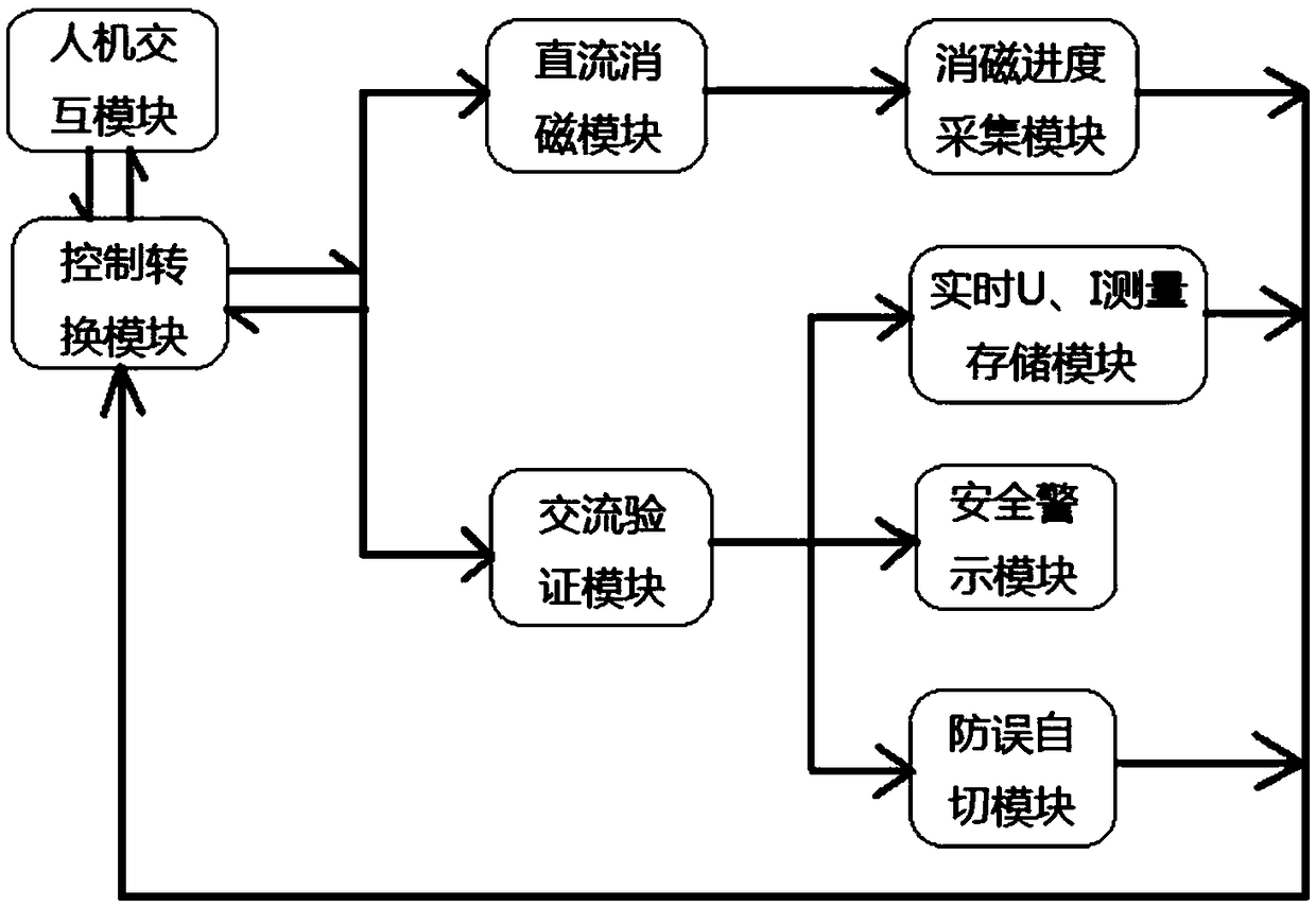
[0029] The working flow chart of the transformer degaussing and verification device is as follows: figure 1 As shown, the transformer degaussing and verification device needs to have the following functions:

[0030] (1) DC degaussing function: limited by the actual operating conditions on site, the device cannot be too heavy and bulky, and the traditional AC degaussing method to eliminate residual magnetism can no longer meet the needs of practical applications. The device developed this time adopts the method of DC degaussing, and can select the gear of the amplitude of the output DC current value during the process of DC degaussing, and display the progress of degaussing during the degaussing process, so as to give the on-site staff a reference on the test time , to prevent blind waiting.

[0031] (2) AC residual magnetism verification function: According to the actual operation status after putting into operation, the power frequency voltage is loaded on the transformer. ...

Embodiment approach

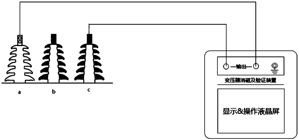
[0044] The wiring of this device is very simple, and the degaussing and verification can be carried out at the low-voltage end of the transformer. Such as figure 2 As shown, according to the practice of testing the DC resistance of large-capacity transformers on site, the DC resistance measurement of the delta-connected low-voltage windings is usually carried out in the order of ab, bc, and ca. The two phases (it is recommended to connect to the pile head of the last two phases tested according to the habit, take ca as an example) are connected to the two terminals of the device, and the operation can be carried out according to the operation process on the panel. That is to measure the excitation current of ca before the DC resistance test of the main transformer and automatically record the data by the device, then use the device to demagnetize ca, measure the excitation current of ca again after degaussing, and compare it with the excitation current before the DC resistanc...


PUM


Abstract

The invention relates to a demagnetizing and verifying apparatus for a transformer. The demagnetizing and verifying apparatus comprises a man-machine interaction module, a control conversion module and a direct current demagnetizing module; the apparatus also comprises an alternating current verifying module; the man-machine interaction module is connected with the control conversion module; the control conversion module is connected with the direct current demagnetizing module and the alternating current verifying module separately; the man-machine interaction module receives an input instruction from an operator, and a digital instruction is converted into an actual operation instruction by the control conversion module; the control conversion module switches connection between the transformer and the direct current demagnetizing module, and between the transformer and the alternating current verifying module according to the actual operation instruction, so as to perform demagnetizing or verifying of the transformer; and for the verification of residual magnetic flux, the residual magnetic flux level of an iron core is judged according to data of an exciting current. Compared with the prior art, the demagnetizing and verifying apparatus has the advantages of rapid verification on residual magnetic flux, short detection time, high demagnetizing efficiency, low cost, convenience in operation, and the like.

Description

technical field [0001] The invention relates to the technical field of power equipment, in particular to a transformer degaussing and verification device. Background technique [0002] After the completion of various electrical tests and maintenance work for large transformers, if the charging operation is carried out without effective degaussing work, the remanence in the transformer core accelerates the saturation of the core, and an excitation inrush current will occur. The non-periodic components and second harmonics of the inrush current will cause the bus voltage distortion of the AC system, causing frequent changes in the commutation angle of the inverters in the surrounding DC converter stations, resulting in DC commutation failure or power fluctuations; Subharmonics may cause AC filter surge arresters to operate or be damaged; continuous excitation inrush current impacts will reduce the mechanical strength of transformer windings, which in turn will lead to a decrea...

Claims


Application Information

Patent Timeline
Patent Type & Authority Patents(China)
IPC IPC(8): H01F13/00G01R33/02G06F3/0481
CPCG01R33/02G06F3/0481H01F13/006
Inventor 徐楠何梦胡明卢静文李荪琪邱毓慜乐佳琪刘隰蒲王俊娜徐敏骅
Owner SHANGHAI MUNICIPAL ELECTRIC POWER CO
Why Eureka
Try Eureka