Integrated circuit of vehicle-mounted charger and DCDC

An on-board charger, integrated circuit technology, applied in battery circuit devices, efficient vehicle charging, electric vehicle charging technology and other directions, can solve the problems of high cost and large assembly space, and achieve low cost, small size and light weight. Effect

Inactive Publication Date: 2017-07-07
SHENZHEN VMAX POWER
View PDF4 Cites 50 Cited by
  • Summary
  • Abstract
  • Description
  • Claims
  • Application Information

AI Technical Summary

Problems solved by technology

In the existing technology, the on-board charger and the DCDC module are separated and independent. Even if they are integ

Method used


Image

  • Integrated circuit of vehicle-mounted charger and DCDC
  • Integrated circuit of vehicle-mounted charger and DCDC
  • Integrated circuit of vehicle-mounted charger and DCDC

Examples


Embodiment 1

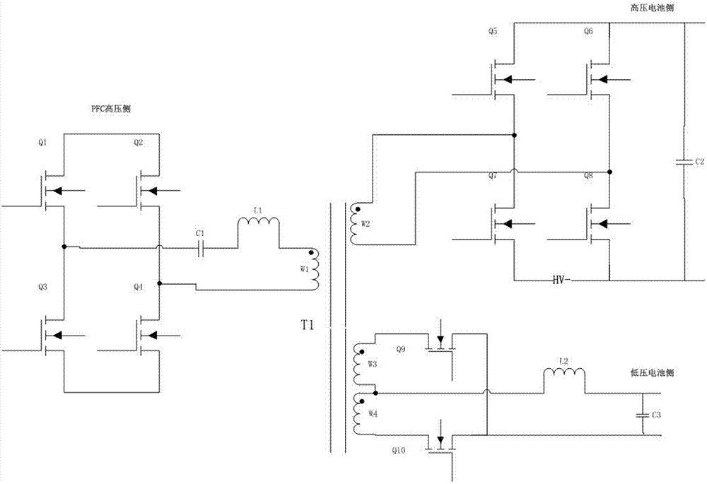
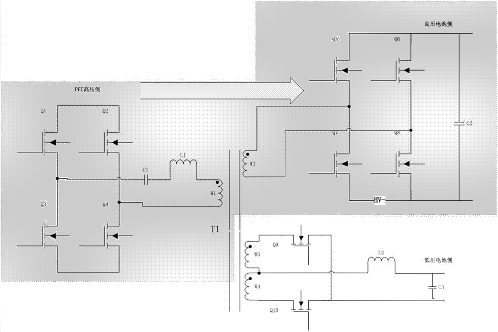
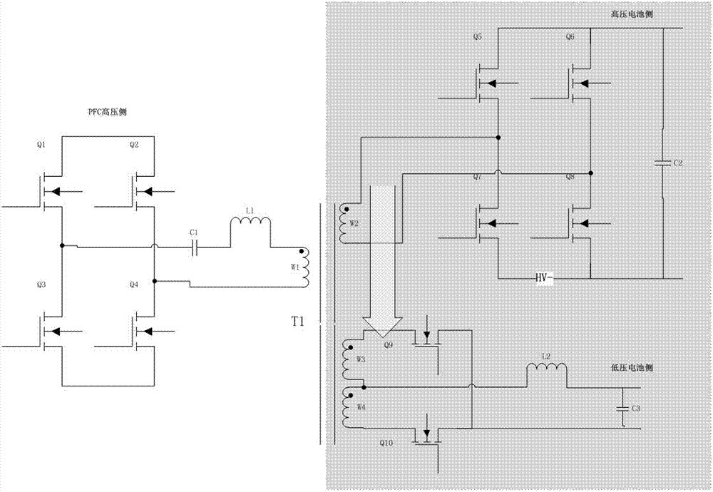
[0032] Such as figure 1 As shown, the power factor correction side circuit connected to the external power factor correction circuit in the integrated circuit includes: first to fourth switch tubes Q1-Q4, and a first capacitor C1. The first to fourth switching tubes Q1-Q4 are connected in series through the source and drain, and the first capacitor C1 and the first winding W1 of the transformer T1 are connected in series between the connecting lines of the first and third switching tubes Q1 and Q3 and the second , between the connection lines of the fourth switching tube; the gates of the first to fourth switching tubes Q1-Q4 are respectively connected to the external control circuit.

[0033] The high-voltage battery side circuit includes: fifth to eighth switching tubes Q5-Q8, and a second capacitor C2. The fifth to eighth switching tubes Q5-Q8 are connected in series through the source and drain, and the second capacitor C2 is connected to the connection line of the fifth ...

Embodiment 2

[0039] Such as Figure 5 As shown, the integrated circuit of this embodiment includes the circuit of Embodiment 1 and a low-voltage voltage stabilizing circuit provided in the low-voltage electrical measuring side circuit for stabilizing the output voltage of the low-voltage battery side.

[0040] The low voltage stabilizing circuit includes eleventh and twelfth switch tubes Q11 and Q12, a fourth capacitor C4 and a third inductor L3. The drain of the eleventh switching tube Q11 and the source of the twelfth switching tube Q12 are respectively connected to both ends of the third capacitor C3, the source of the eleventh switching tube Q11 is connected to the drain of the twelfth switching tube, The fourth capacitor C4 and the third inductor L3 are connected in series at both ends of the twelfth switching tube Q12; both ends of the fourth capacitor C4 are low-voltage output ends.

Embodiment 3

[0042] Such as Image 6 As shown, the power factor correction side circuit connected to the external power factor correction circuit in the integrated circuit of this embodiment includes: the first and third switch tubes Q1 and Q3, the first capacitor C1, and the first and third switch tubes through The source and the drain are connected in series at both ends of the power factor correction circuit, and the first capacitor C1 and the first winding W1 of the transformer T1 are connected in series and then connected in parallel at both ends of the source and the drain of the third switching tube Q3.

[0043] The high voltage battery side circuit and the low voltage battery side circuit in the integrated circuit of this embodiment are the same as those in the first embodiment.

[0044] In any of the above embodiments, the power factor correction side circuit can also be provided with a first inductor L1, and the first inductor L1 is connected in series between the first capacitor...


PUM


Abstract

The invention discloses an integrated circuit of a vehicle-mounted charger and a DCDC. The integrated circuit comprises a power factor correction side circuit connected with a power factor correction circuit, a high-voltage battery side circuit connected with a high-voltage battery circuit, a low-voltage battery side circuit connected with a low-voltage battery circuit, and a transformer T1 coupled with the three circuits. The integrated circuit integrates the vehicle-mounted charger and a high-power DCDC module which are independent, shares a power switching tube and a control circuit, shares a magnetic core for energy delivery, can flexibly realize control and switching of a charger mode, a DCDC mode and an inversion mode, and is concise and ingenious in design, small in size, light in weight and low in cost.

Description

technical field [0001] The invention relates to the technical field of electric vehicle charging, in particular to an integrated circuit of a vehicle charger and a DCDC. Background technique [0002] With the increasing requirements for energy saving, emission reduction and air pollution control, new energy vehicles are gradually commercialized in the market, and electric vehicles are the main force of new energy vehicles. Electric vehicles are further divided into pure electric vehicles and hybrid vehicles, among which on-board chargers and high-power DCDC are important components of electric vehicles. However, in the prior art, the on-board charger and the DCDC module are scattered and independent. Even if they are integrated, they are also assembled and integrated at the physical level, resulting in large assembly space and high cost. Contents of the invention [0003] The object of the present invention is to provide an integrated circuit of an on-board charger and a ...

Claims


Application Information

Patent Timeline
IPC IPC(8): H02J7/00B60L11/18
CPCB60L53/22H02J7/0068H02J2207/20Y02T10/70Y02T10/7072Y02T10/72Y02T10/92Y02T90/14
Inventor 刘钧冯颖盈徐金柱
Owner SHENZHEN VMAX POWER
Why Eureka
Try Eureka