Bulletproof armor device integrating synergy deformation clamp

A bulletproof and armored plate technology, which is applied to the structure, armor, protective equipment and other directions of the armored plate, can solve the problems of large deformation of the bulge of the back plate and the surrounding tightening, so as to increase the bulletproof ability and facilitate installation. Effect

Active Publication Date: 2017-07-11
HUNAN UNIV
View PDF7 Cites 4 Cited by
  • Summary
  • Abstract
  • Description
  • Claims
  • Application Information

AI Technical Summary

Problems solved by technology

Chinese patent CN103868413A discloses a bullet-proof plate with ceramics in front and composite laminates in the back, but actual tests show that the protrusions on the back plate are greatly deformed, resulting in serious tightening around

Method used


Image

  • Bulletproof armor device integrating synergy deformation clamp
  • Bulletproof armor device integrating synergy deformation clamp
  • Bulletproof armor device integrating synergy deformation clamp

Examples


Embodiment 1

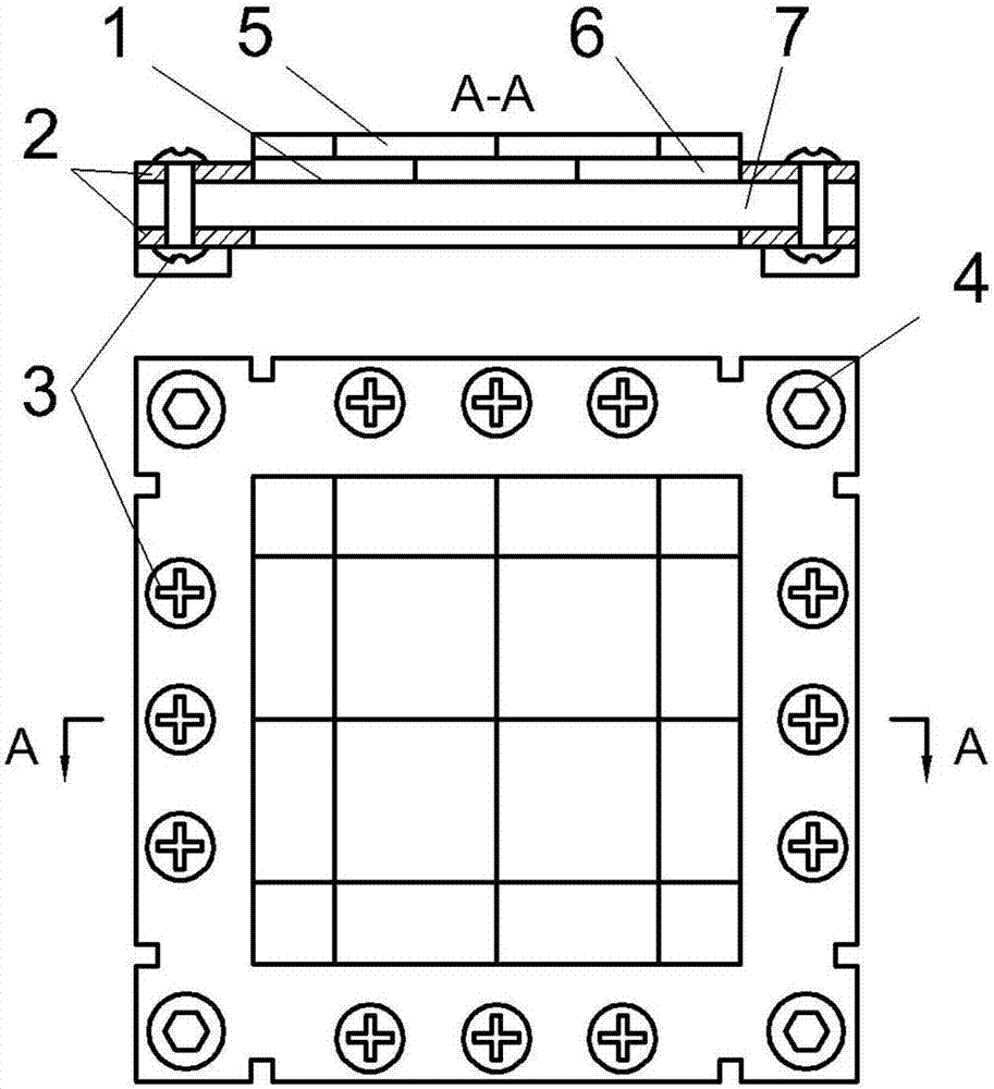
[0031] The invention provides a device for coordinating the deformation and energy absorption of laminated plates of composite materials. Its specific structure includes: an armor plate 1, an annular frame cooperating deformation clamp 2, rivets 3 and bolts 4, and the armor plate is installed as follows: figure 1 As shown, the A-A sectional view of this schematic diagram has removed the fastening bolts; wherein the armor plate 1 includes: the first layer of ceramic panels 5, the second layer of ceramic panels 6 and the back plate ultra-high molecular weight polyethylene laminate 7, the armor plate The size is small, and the specific size can be adjusted according to the bulletproof requirements.

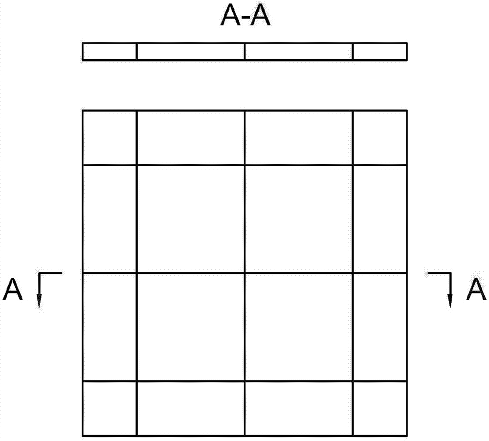
[0032] The first layer of ceramic panels 5 is spliced ​​by large square ceramics, rectangular ceramics and small square ceramics, the area of ​​the small square ceramics is 1 / 4 of the large square ceramics, and the area of ​​the rectangular ceramics is 1 / 2 of the large square ceramics...

Embodiment 2

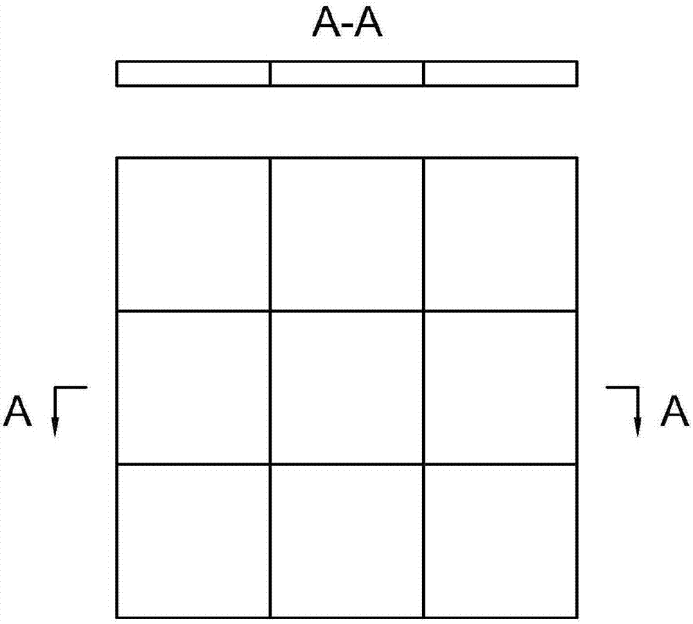
[0041] The invention provides a device for coordinating the deformation and energy absorption of laminated plates of composite materials. The specific structure includes: an armor plate 1, an annular frame cooperative deformation fixture 2, rivets 3 and bolts 4, wherein the armor plate includes: a first layer of ceramic panels 5. The second layer of ceramic panel 6 and the back panel ultra-high molecular weight polyethylene laminate 7, but compared with Example 1, the size of the armor plate in Example 2 is increased; after the armor plate is impacted, the back of the laminate will bulge , four-sided tightening, interlayer separation and other failure phenomena, because the laminate at this time is thicker, the backside interlayer separation will become more serious.

[0042] Armor plate with increased size and thicker thickness, in which the overall size of the ceramic panel is 250×250×12mm, the spliced ​​ceramics used are the same as in Example 1, the area of ​​the laminated ...


PUM

PropertyMeasurementUnit
lengthaaaaaaaaaa
diameteraaaaaaaaaa

Abstract

The invention relates to a bulletproof armor device integrating a synergy deformation clamp. The device comprises an armor 1, the synergy deformation clamp 2, rivets 3 and a bolt 4; the armor 1 is a dual-layer ceramic layer, uses a composite material as a back plate, and comprises a first-layer cylindrical ceramic joint layer 5 and a second-layer cylindrical ceramic joint layer 6, the composite material back plate is an ultra-high molecular weight polyethylene laminate 7, and all layers are bonded through a cementing compound; the four edges of the armor 1 and the four edges of the synergy deformation clamp 2 are riveted together through the rivets; and when the armor is shot by a bullet, the synergy deformation clamp 2 with a weakening groove can deform along with the back plate. By means of the bulletproof armor device, the double layers of ceramic panels are free of bullet-proof weak areas, the synergy deformation clamp can improve the supporting capacity of the back plate, the overall bulletproof property of the ceramic composite armor can be obviously improved, and meanwhile, the armor can be conveniently installed and replaced.

Description

technical field [0001] The invention relates to a bulletproof armor plate and its installation structure, which is a device for coordinating the deformation of laminated plates of composite materials. Background technique [0002] Since the birth of ceramic composite armor, it has played a pivotal role in warfare, and ceramic composite armor is developing in the direction of lightweight and high performance. In order to prevent the damage area of ​​ceramic composite armor from being too large in one shot and improve the armor's anti-strike protection ability, the ceramic layer is usually spliced ​​with small-sized ceramics, but it also brings other problems. The disadvantage of the composite armor spliced ​​by single-layer ceramics is that the bulletproof ability of the adjacent ceramic splicing interface is very poor, which is the weak area of ​​bulletproof. In addition, the installation of ceramic composite armor is also a very important issue, and the installation time s...

Claims


Application Information

Patent Timeline
Patent Type & Authority Applications(China)
IPC IPC(8): F41H5/04B32B9/00B32B9/04B32B18/00B32B27/32B32B3/14B32B3/22B32B7/12
CPCB32B3/14B32B3/18B32B7/12B32B9/005B32B9/04B32B9/045B32B27/32B32B2571/02F41H5/0428
Inventor 胡德安张友敏沈志伟蔡清裕刘丽侯淑娟
Owner HUNAN UNIV
Why Eureka
Try Eureka