
A high-precision laser 3D profile detection method for mobile phone structural parts

A technology of mobile phone structure and detection method, which is applied to measurement devices, optical devices, instruments, etc., can solve the problems of inaccurate detection results, large data disturbance, long training and learning, etc., and achieve false positives and false negatives. The effect of low probability, high accuracy of detection data, and high degree of flexibility

Active Publication Date: 2019-11-29
深圳市深视智能科技有限公司
View PDF6 Cites 2 Cited by
  • Summary
  • Abstract
  • Description
  • Claims
  • Application Information

AI Technical Summary

Problems solved by technology

This 2D vision method has large data disturbances, and often small changes in light intensity, material changes, and light source angles will have a great impact on the data, and the detection results are inaccurate.
Some AOI manufacturers use statistical machine learning methods and three-color LED multi-angle light sources to manufacture image inspection equipment, which can detect the presence or absence of defects to a certain extent, but cannot accurately quantify defects in size
[0003] 1 Conventional 2D machine vision uses the method of taking pictures from the front or side, and the image features are easily affected by the light, resulting in false detection results;
[0004] 2. Another way to deal with surface detection is to use intelligent image algorithms, such as machine learning methods for image feature classification, and achieve classification through a large number of sample training, but this method cannot quantify the size, and it takes a long time for training and study;
[0005] 2. The current laser profilometer can output surface point cloud, but the measurement width is narrow, the accuracy and efficiency are not ideal, and the measurement of mixed materials is not reliable
[0006] 3. Using depth data for detection involves 3D point cloud registration. The current mainstream 3D point cloud registration algorithm is an iterative nearest neighbor algorithm (ICP) adapted to free-form surface registration. It is inefficient for 3D visual detection and cannot Meet online testing needs

Method used

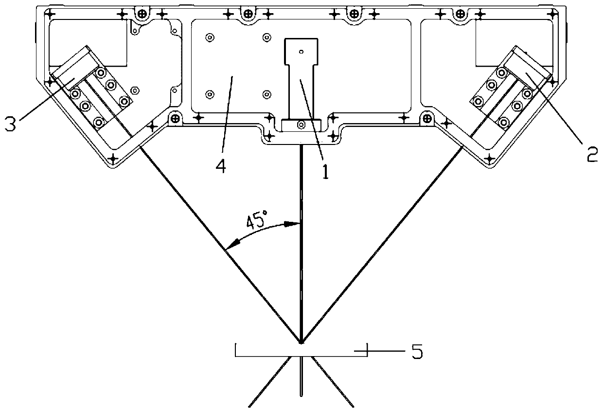
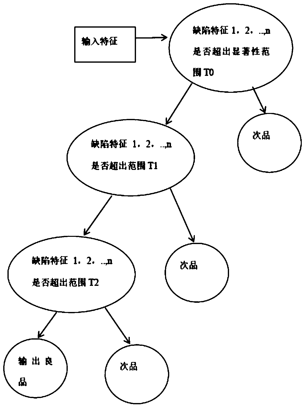

Image

  • A high-precision laser 3D profile detection method for mobile phone structural parts
  • A high-precision laser 3D profile detection method for mobile phone structural parts
  • A high-precision laser 3D profile detection method for mobile phone structural parts

Examples


Embodiment Construction

[0048]The implementation of the present invention will be described in detail below in conjunction with the accompanying drawings and examples, so as to fully understand and implement the process of how to apply technical means to solve technical problems and achieve technical effects in the present invention. It should be noted that, as long as there is no conflict, each embodiment and each feature in each embodiment of the present invention can be combined with each other, and the formed technical solutions are all within the protection scope of the present invention.

[0049] In addition, the steps shown in the flow diagrams of the figures may be performed in a computer system, such as a set of computer-executable instructions, and, although a logical order is shown in the flow diagrams, in some cases, the sequence may be different. The steps shown or described are performed in the order herein.

[0050] Wherein, the process of the method for measuring mobile phone structur...


PUM


Abstract

The invention discloses a high-precision laser 3D profile detection method of a mobile phone structure piece. The detection method comprises steps of step 1), using a laser measurement device to scan a sample once, setting scanning parameters including laser power, image exposure time and acquisition range, and sampling laser scanning image samples of the sample; step 2), placing a mobile phone structure piece to a moving work bench, fixing a laser measurement head right above the mobile phone structure piece and using a servo motor to drive a work bench support plate to move, thereby finishing the detection, wherein the system finishes the surface profile detection in two seconds, the sampling frequency St=pl / sstep, the pl is the measurement length of a product and the sstep is the sampling step length; step 3), establishing a profile standard data model; and step 4, importing 3D model CAD data before measurement, wherein the data is formed by thousands or tens of thousands of triangular face sheets, and intercepting the slice graph of a 3D model along a path perpendicular to the scanning direction.

Description

technical field [0001] The invention belongs to a high-precision laser 3D profile mobile phone structural component detection method. Background technique [0002] With the development of mobile terminals (mobile phones), the quality requirements of mobile phone structural parts are getting higher and higher. In the past, most manufacturers of mobile phone structural parts mainly used visual observation, which was very subjective and difficult to stabilize the quality. A small number of companies in the industry use machine vision methods to detect mobile phone structural parts, such as Huawei Technologies Co., Ltd., Samsung, etc., and have also deployed some test equipment to mobile phone production lines. The mainstream of these test equipment and detection systems still use 2D vision technology. The contours are photographed using light sources from different angles, and then analyzed and processed using image processing algorithms. This 2D vision method has large data ...

Claims


Application Information

Patent Timeline
Patent Type & Authority Patents(China)
IPC IPC(8): G01B11/24
CPCG01B11/24
Inventor 金少峰王刚奎王晓东
Owner 深圳市深视智能科技有限公司
Learn More