
Charge pump circuit based on steady-state anti-leakage protection and current sink control technology

A current sink and charge pump technology, applied in the direction of automatic power control, electrical components, output power conversion devices, etc., can solve the problems of the development limit of the charge pump phase-locked loop, the difficulty of realizing the charge pump, and the control voltage stability, etc. The working conditions are easy to meet, easy to realize, and easy to integrate.

Active Publication Date: 2020-05-26
拓尔微电子股份有限公司
View PDF5 Cites 0 Cited by
  • Summary
  • Abstract
  • Description
  • Claims
  • Application Information

AI Technical Summary

Problems solved by technology

For compound semiconductors, the process has only N-type transistors and no P-type (complementary) transistors, which makes it difficult to match the current source and current sink, which makes it difficult to realize the charge pump. Therefore, the compound semiconductor charge pump phase-locked loop development is severely restricted
[0005] At present, for compound semiconductor charge pumps, the method of controlling the current sink current is used to solve the mismatch problem between the current source and the current sink, but this method is difficult to accurately match the current magnitude of the current sink and the current source. In the steady state, it is impossible to truly stabilize the control voltage output by the charge pump

Method used


Image

  • Charge pump circuit based on steady-state anti-leakage protection and current sink control technology

Examples


Embodiment Construction

[0019] The following will clearly and completely describe the technical solutions in the embodiments of the present invention with reference to the accompanying drawings in the embodiments of the present invention. Obviously, the described embodiments are only some, not all, embodiments of the present invention. Based on the embodiments of the present invention, all other embodiments obtained by persons of ordinary skill in the art without making creative efforts belong to the protection scope of the present invention.

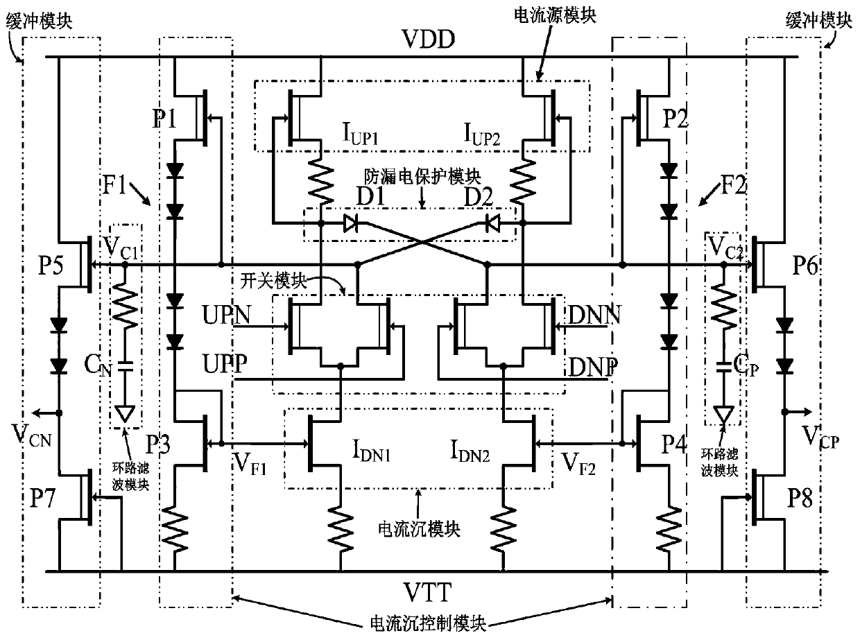
[0020] refer to figure 1, the charge pump circuit based on steady-state anti-leakage protection and current sink control technology provided in the embodiment of the present invention includes an anti-leakage protection module, a current sink control module, a switch module, a current sink and a current source module, a loop filter module, and buffer module. The overall charge pump circuit is in differential form, and the process is a compound semiconductor p...


PUM


Abstract

The invention discloses a charge pump circuit based on a steady-state electric leakage protection and current sink control technology, and relates to the technical field of circuit designs. The circuit comprises an electric leakage protection module, a current sink control module, a switch module, a current sink and current source module, a loop filtering module and a buffer module. The charge pump does not accurate matching of the current sink and the current source of the circuit, only needs to meet the condition that the current of the current sink is more than or equal to that of the current source. Therefore, operation conditions of the circuit are more prone to meet, and the compound semiconductor charge pump is more prone to implement. Meanwhile, the electric leakage protection module is achieved by two diodes, so that the module is simple in structure, does not additionally occupy excessive chip area, and is more convenient to integrate. An electric leakage problem caused by mismatching of the current source and the current sink in a steady-state can be solved by unilateral conductivity of the diodes in an electric leakage protection technology, and thus a control voltage output by the charge pump circuit in the case of steady-state is unchanged.

Description

technical field [0001] The invention relates to the technical field of circuit design, in particular to a charge pump circuit based on steady-state anti-leakage protection and current sink control technology. Background technique [0002] With the continuous development of personal wireless communication, radar, terahertz technology and space communication, higher requirements are placed on the transceiver system, including higher frequency, wider bandwidth, higher integration and more Great power etc. The variable frequency source is an important part of the transceiver, and its performance will directly determine the performance of the transceiver. At present, compared with SiCMOS and SiGe BiCMOS processes, compound semiconductor processes have better frequency and power characteristics and are more suitable for designing high-performance variable frequency sources. [0003] Common direct digital frequency synthesizers, charge pump phase-locked loop frequency synthesizer...

Claims


Application Information

Patent Timeline
Patent Type & Authority Patents(China)
IPC IPC(8): H03L7/089H02M1/32
CPCH02M1/32H03L7/0891
Inventor 吕红亮武岳唐铭浩张玉明张义门
Owner 拓尔微电子股份有限公司
Learn More