
Flexible composite forming method of cylindrical member with grid ribs

A technology of composite forming and grid ribs, which is applied in the field of flexible composite forming of tubular members with grid ribs, can solve problems such as complex process, high technical requirements, and forming defects, and achieve expanded forming range, high forming accuracy and low cost. low effect

Active Publication Date: 2017-07-21
WUHAN UNIV OF TECH
View PDF5 Cites 9 Cited by
  • Summary
  • Abstract
  • Description
  • Claims
  • Application Information

AI Technical Summary

Problems solved by technology

However, it can be seen from the analysis of the reported situation that these new methods still have many limitations
First of all, they are only used to form simple inner surface transverse or longitudinal rib structures, and have not yet involved complex grid rib structures, and the process is complicated, the technical requirements are high, and various forming defects are prone to occur; secondly, their forming size range Limited by the processing capacity of the equipment, it is currently only suitable for small and medium-sized cylindrical parts with a diameter of about 1 meter; moreover, they need special equipment and molds, and due to the limitation of the processing range of special equipment, products of different specifications require different Equipment and molds, high investment
Due to these technical limitations, the above methods seem to be powerless for large thin-walled cylindrical members with grid ribs. Therefore, it is urgent to develop new high-performance, high-efficiency, and low-cost forming technologies for large thin-walled cylindrical members with grid ribs to meet Advanced Aerospace and Weapon Equipment Development Requirements

Method used


Image

  • Flexible composite forming method of cylindrical member with grid ribs
  • Flexible composite forming method of cylindrical member with grid ribs
  • Flexible composite forming method of cylindrical member with grid ribs

Examples


Embodiment Construction

[0028] Specific embodiments of the present invention are described in detail below, which, as a part of the description, illustrate the principle of the present invention through examples, and other aspects, features and advantages of the present invention will become clear through the detailed description.

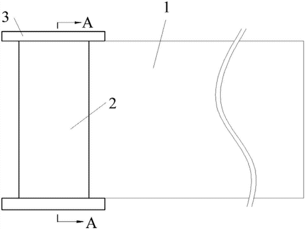
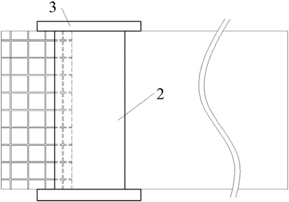
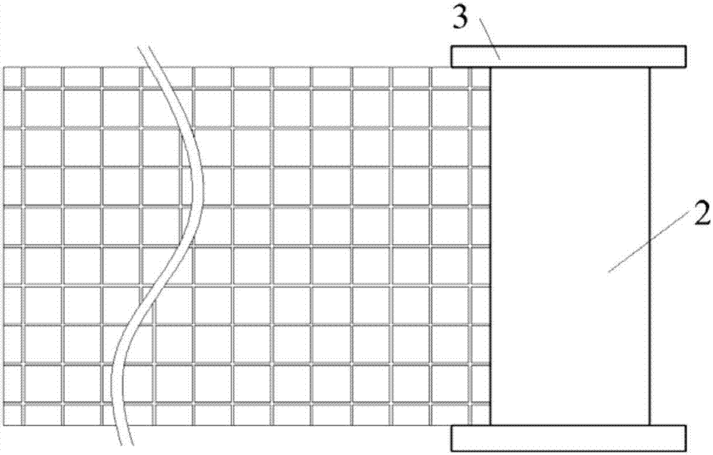
[0029] As shown in Figure 1-7, it is a structural schematic diagram of a flexible composite forming method for a cylindrical member with grid ribs according to a preferred embodiment of the present invention. The method for flexible composite forming of a cylindrical member with grid ribs in the present invention includes the following steps:

[0030] Step 1. Select a flat blank 1 of suitable size and specification according to the size of the target component. The width of the flat blank 1 is equal to the height of the target component, the length of the flat blank 1 is equal to the circumference length of the target component, and the thickness of the flat blank 1 is equa...


PUM


Abstract

The invention discloses a flexible composite forming method of a cylindrical member with grid ribs. The method comprises the following steps that a panel billet is selected according to the size of the target member; the panel billet is placed onto a workbench of a press machine along a guide plate; an integrated grid rib structure is extruded on the whole billet through a continuous local extruding method, so that a planar grid plate is obtained; then a curved-face grid plate of the grid rib structure is formed by means of a three-roll bending method; and finally, the cylindrical element with the grid ribs is formed by means of a welding method. According to the flexible composite forming method, plastic working and welding are organically combined, the cylindrical member with the grid ribs can be formed precisely, efficiently and flexibly, the product quality and manufacturing efficiency are improved, the manufacturing cost is lowered, and the manufacturing range is expanded.

Description

technical field [0001] The invention relates to a flexible composite forming method of a cylindrical member with grid ribs. Background technique [0002] The cylindrical member with grid ribs is a key high-performance lightweight component for new aerospace and weaponry. This type of member is mainly made of aluminum alloy lightweight materials, with a large diameter and thin wall, and a criss-cross grid rib structure on the surface. The material is difficult to deform and the structure is difficult to form special components. The traditional manufacturing method of such components is usually to obtain a seamless or seamed cylindrical substrate by means of plastic forming such as spinning or sheet metal bending and welding, and then perform rib welding and cutting on the surface to obtain a grid tendon structure. The processing method of grid bars based on welding and cutting is not only very inefficient, but also a large number of welds have caused obvious limitations and...

Claims


Application Information

Patent Timeline
IPC IPC(8): B21D35/00B21D31/00B21D5/14
CPCB21D5/14B21D31/00B21D35/005
Inventor 华林邓加东钱东升兰箭
Owner WUHAN UNIV OF TECH
Learn More