Aftertreatment method of 3D printing part

A 3D printing and parts technology, applied in 3D object support structures, metal processing equipment, manufacturing tools, etc., can solve the problems of poor mechanical properties of parts, achieve the effect of strengthening mechanical properties and shortening processing time

Active Publication Date: 2017-07-21
四川长虹智能制造技术有限公司
View PDF11 Cites 5 Cited by
  • Summary
  • Abstract
  • Description
  • Claims
  • Application Information

AI Technical Summary

Problems solved by technology

[0007] The technical problem to be solved by the present invention is that the problem of poor mechanical properties of parts caused by the accumulation gap of 3D printing parts in the prior art cannot be effectively solved, and further provides a method that can effectively solve the problem of poor mechanical properties of parts caused by the accumulation gap of 3D printing parts, and is environmentally friendly. 3D printing parts post-processing method

Method used


Image

  • Aftertreatment method of 3D printing part
  • Aftertreatment method of 3D printing part

Examples


Embodiment 1

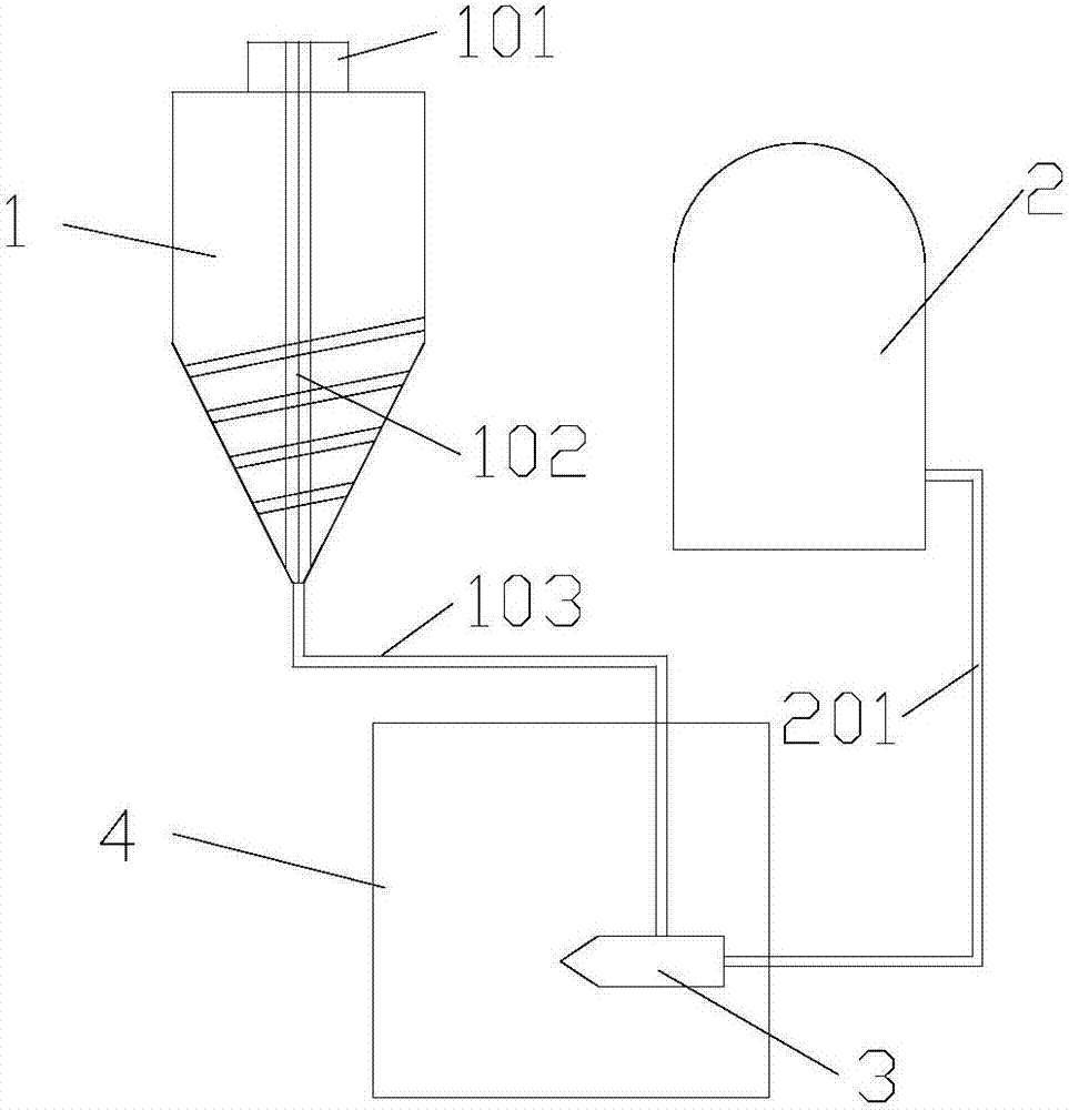
[0036] In this embodiment, the post-processing method of the 3D printed parts includes the following steps:

[0037] (1) The diameter of 2kg is 0.2mm, the micropore diameter is 300nm, and the specific surface area is 100m 2 / g, the glass microspheres are completely placed in dimethylformamide solvent, stirred and placed for 1h;

[0038] (2) Filter out the glass microbeads after absorbing dimethylformamide solvent, and then place the glass microbeads after absorbing dimethylformamide solvent in the feed device, wherein the feed of the feed device The method is spiral extrusion;

[0039] (3) The glass microbead medium after absorbing the dimethylformamide solvent is transported to the spray gun by screw extrusion in the feeding device, wherein the rotating speed of the screw extrusion rod during screw extrusion is 60 rpm;

[0040] (4) 3D printing parts are placed in a post-processing chamber with a sealed door, and the glass beads after the adsorption of dimethylformamide solv...

Embodiment 2

[0042] In this embodiment, the post-processing method of the 3D printed parts includes the following steps:

[0043] (1) The diameter of 2kg is 0.5mm, the pore diameter is 80nm, and the specific surface area is 400m 2 The ceramic microbead of / g is placed in the dichloromethane solvent completely, stirs and places 4h;

[0044] (2) Filter out the ceramic microbeads after absorbing methylene chloride solvent, then place the ceramic microbeads after absorbing methylene chloride solvent in the feeding device, wherein the feeding mode of the feeding device is screw extrusion out;

[0045] (3) The ceramic microbeads after absorbing the methylene chloride solvent are transported to the spray gun in the feeding device by means of screw extrusion, wherein the rotating speed of the screw extrusion rod during screw extrusion is 240 rpm;

[0046] (4) 3D printing parts are placed in a post-processing chamber with a sealed door, and the ceramic microbeads after the adsorption of dichlorom...

Embodiment 3

[0048] In this embodiment, the post-processing method of the 3D printed parts includes the following steps:

[0049] (1) The diameter of 3kg is 0.4mm, the micropore diameter is 120nm, and the specific surface area is 300m 2 / g of ceramic microbeads is completely placed in acetone solvent, stirred and placed for 3.5h;

[0050] (2) filtering out the ceramic microbeads after absorbing the acetone solvent, and then placing the ceramic microbeads after absorbing the acetone solvent in the feeding device, wherein the feeding mode of the feeding device is screw extrusion;

[0051] (3) The ceramic microbeads after absorbing the acetone solvent are transported to the spray gun in the feeding device by means of screw extrusion, wherein the rotating speed of the screw extrusion rod during screw extrusion is 180 rpm;

[0052] (4) The 3D printed parts are placed in a post-processing chamber with a sealed door, and the ceramic microbeads after the adsorption of acetone solvent enter the ai...


PUM

PropertyMeasurementUnit
diameteraaaaaaaaaa
pore sizeaaaaaaaaaa
specific surface areaaaaaaaaaaa

Abstract

The invention provides an aftertreatment method of a 3D printing part and belongs to the technical field of 3D printing. The aftertreatment method of the 3D printing part comprises the following steps that (1), a certain amount of a micro-bead medium with micro holes is completely placed into a solvent, and stirring and standing are conducted for a certain time; (2), the micro-bead medium subjected to solvent adsorption is filtered out, and then the micro-bead medium subjected to solvent adsorption is placed into a micro-bead medium feeding device; (3), the micro-bead medium subjected to solvent adsorption is conveyed to a spray gun by the micro-bead medium feeding device; and (4), the micro-bead medium subjected to solvent adsorption and located in the sprayed gun is sprayed to the treated surface of the 3D printing part through high-pressure air to treat the surface of the 3D printing part, and the surface of the 3D printing part is composed of a polymer forming material. By adoption of the aftertreatment method of the 3D printing part, after the surface of the 3D printing part is treated, a smooth surface can be obtained, the mechanical property of the 3D printing part in the Z-axis forming direction can be improved, and the aftertreatment method of the 3D printing part has the outstanding beneficial effects.

Description

technical field [0001] The invention relates to a post-processing method for 3D printing parts, belonging to the technical field of 3D printing. Background technique [0002] As one of the advanced manufacturing technologies, 3D printing technology has digital and intelligent manufacturing at its core. It changes the processing mode of cutting and assembling raw materials, and realizes anytime, anywhere, on-demand production. 3D printing technology has entered the initial stage of industrialization and practicality. It will bring comprehensive and profound changes to product design, manufacturing process, manufacturing equipment and production line, material preparation, related industrial standards, manufacturing enterprise form and even the entire traditional manufacturing system. [0003] The application of 3D printing technology can produce high-quality parts, but its principle is to use digital model files as the basis, and use plastic, metal, inorganic non-metal and ot...

Claims


Application Information

Patent Timeline
Patent Type & Authority Applications(China)
IPC IPC(8): B29C64/379B33Y40/00
CPCB33Y40/00
Inventor 潘晓勇刘勇余刚彭德权刘佳其周未名
Owner 四川长虹智能制造技术有限公司
Why Eureka
Try Eureka