Anti-shear peg

A shear-resistant stud and stud technology, which is applied to measuring devices, instruments, scientific instruments, etc., can solve the problem of low shear-resistant bearing capacity, and achieve the effects of saving materials, easy operation, and simple improvement methods.

Active Publication Date: 2017-07-21
HARBIN INST OF TECH
View PDF5 Cites 3 Cited by
  • Summary
  • Abstract
  • Description
  • Claims
  • Application Information

AI Technical Summary

Problems solved by technology

[0004] The purpose of the present invention is to solve the problem of low shear bearing cap

Method used


Image

  • Anti-shear peg
  • Anti-shear peg
  • Anti-shear peg

Examples


specific Embodiment approach 1

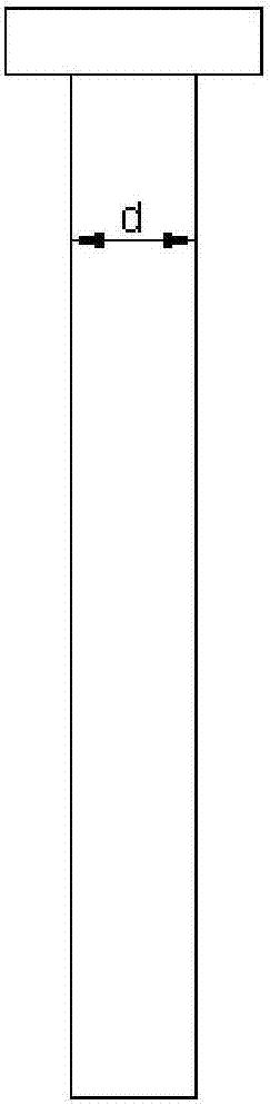
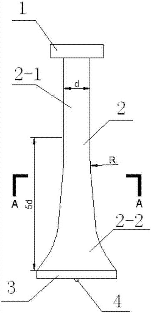
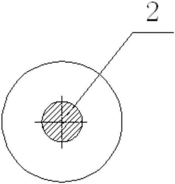
[0016] Specific embodiment 1: The shear stud of this embodiment includes a stud rod 2 and a cap 1, and a cap 1 is arranged on the top of the stud rod 2, and the diameter of the upper shaft 2-1 of the stud rod 2 is is d, the lower shaft 2-2 of the stud rod 2 is in the shape of a trumpet cone and the diameter of the shaft gradually increases with the axial direction downward of the stud rod, and the height of the lower shaft 2-2 of the stud rod 2 is 5d , The diameter of the bottom of the peg rod 2 is 2-2.5d, and the bottom of the peg rod 2 is also provided with a cylindrical bottom section 3 .

[0017] The peg rod, the peg cap and the bottom section of the cylinder described in this embodiment are integrally structured. Smooth rounded transition between upper shaft and lower shaft.

[0018] The shear studs in the steel-concrete composite structure of this embodiment design the optimization curve of the stud section diameter along the height through the finite element analysis, ...

specific Embodiment approach 2

[0021] Embodiment 2: This embodiment differs from Embodiment 1 in that the diameter of the peg rod 2 is 1.2-1.4d at the height of the lower shaft 2-2 of the peg rod 2 at a height of d.

specific Embodiment approach 3

[0022] Embodiment 3: This embodiment differs from Embodiment 2 in that the diameter of the peg rod 2 is 1.1-1.2d at the height of the lower shaft 2-2 of the peg rod 2 at a height of 3d.


PUM

PropertyMeasurementUnit
Thicknessaaaaaaaaaa
Diameteraaaaaaaaaa
Elastic modulusaaaaaaaaaa

Abstract

The invention relates to pegs in steel-concrete composite structure, in particular to an anti-shear peg, and is intended to solve the problem that an existing peg has poor ant-wear bearing capacity during repeated loading. The anti-shear peg comprises a shank and a cap, the cap is arranged at the top of the shank, the diameter of the upper portion of the ant-shear peg is d, the lower portion of the shank is in the shape of a horn cone, the height of the lower portion of the shank is 5d, and the bottom diameter of the shank is 2-2.5 d and is also provided with a cylindrical bottom segment. The shape of the existing peg is modified, maximum stress of the peg is lowered, the yield limit anti-shear bearing capacity is improved under repeated loading effect, stress of a heat influencing area of a welding connector is reduced, stress of a heat-thermal influencing area of the welding connector is decreased, the shape of the shank is optimized so that plastic strain is transferred to a peg itself having good extensibility in a 4-time diameter range, and ultralow periodic fatigue under repeated loading action for the welding head is avoided.

Description

technical field [0001] The present invention relates to studs in steel-concrete composite structures. Background technique [0002] At present, as a common shear connector, studs are widely used in steel-concrete composite structures. Common studs mainly include two parts: studs and bolt caps. The commonly used welding method is stud welding, which is a high-pressure Fusion welding method. According to previous experimental research results and finite element analysis results, the shear bearing capacity provided by the studs is mainly determined by the studs and welded joints within 4 times the diameter of the connection between the studs and the plate (or pipe), among which The stress of the welded joint is the most concentrated and complex. The stress value of the stud within the range of 4 times the diameter is higher, and the stress beyond the range of 6 times the diameter is basically unchanged. [0003] According to the test results of the shear bearing capacity of t...

Claims


Application Information

Patent Timeline
IPC IPC(8): G01N3/04G01N3/32
CPCG01N3/04G01N3/32G01N2203/0005
Inventor 翟长海路冰李爽温卫平谢礼立
Owner HARBIN INST OF TECH
Why Eureka
Try Eureka