Vehicle-borne radar in-loop real-time simulation test system and method thereof

A technology of real-time simulation and vehicle-mounted radar, which is applied to radio wave measurement systems, measurement devices, instruments, etc., can solve the problems that the trajectory of dynamic obstacles is difficult to set, the radar accuracy cannot be effectively tested, and the radar test method has not been proposed. It is convenient and quick to change the path, convenient and quick to arrange, and the effect of shortening the test cycle

Active Publication Date: 2017-07-21
HEFEI UNIV OF TECH
View PDF10 Cites 26 Cited by
  • Summary
  • Abstract
  • Description
  • Claims
  • Application Information

AI Technical Summary

Problems solved by technology

[0003] The existing radar test system cannot realize the effective test of radar accuracy
Chinese patent 201510416151.X "a radar test bench" fixes the radar on the bench for measurement, which can meet the requirements of various test environments, but the radar test bench involved in this patent is also used in the actual test environment and No method proposed for radar testing
Chinese patent 201610749771.X "A Millimeter-Wave Radar Test System" proposes a millimeter-wave radar test system, which uses real static obstacles and dynamic obstacles sliding on the track to test outdoors, which is not only costly, but also For different test environments, the experimental environment needs to be re-arranged. The trajectory of complex dynamic obstacles is not easy to set up, and the test is difficult.
Chinese patent 200610083479.5 "A Millimeter Wave Agile Radar Simulator" proposes a millimeter wave agile radar simulator, which uses distance simulation and signal delay to detect radar tracking performance, but it cannot realize various vehicle road conditions The test method for the radar and the detection angle of the radar is not involved

Method used


Image

  • Vehicle-borne radar in-loop real-time simulation test system and method thereof
  • Vehicle-borne radar in-loop real-time simulation test system and method thereof
  • Vehicle-borne radar in-loop real-time simulation test system and method thereof

Examples


Embodiment Construction

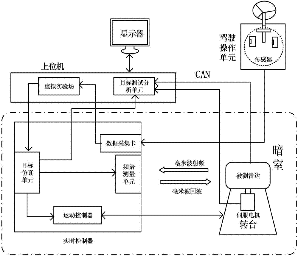
[0042] In this embodiment, a vehicle-mounted radar-in-the-loop real-time simulation test system, such as figure 2 As shown, including: the radar under test, driving operation unit, display, real-time controller and host computer on the turntable; the radar under test and real-time controller are in the dark room;

[0043] The driving operation unit includes: a driving operation mechanism and a driving operation signal sensor; the driving operation mechanism includes: a steering wheel, an accelerator pedal and a brake pedal; the driving operation signal sensor includes: a steering wheel angle sensor, an accelerator pedal position sensor and a brake pressure sensor;

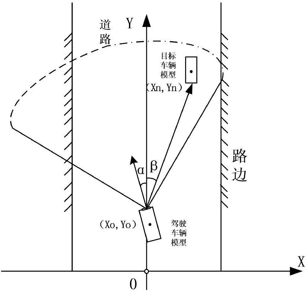
[0044] The upper computer includes: a virtual test field and a target test analysis unit; such as figure 1 As shown, the virtual proving ground includes: the driving vehicle model and the target vehicle model, which are displayed in real time through the monitor; the driving vehicle model is used to virtually load...


PUM


Abstract

The invention discloses a vehicle-borne radar in-loop real-time simulation test system and a method thereof. The system comprises a tested radar located on a turntable, a driving operation unit, a display, a real-time controller and an upper computer, wherein the driving operation unit comprises a driving operation mechanism and a driving operation signal sensor; the upper computer comprises a virtual test field and a target test and analysis unit; a driving vehicle model and a target vehicle model are included in the virtual test field; the driving vehicle model is used for virtually loading the tested radar; the real-time controller comprises a spectrum measurement unit, a target simulation unit, a motion controller and a data acquisition card; and the spectrum measurement unit comprises a millimeter wave signal transceiver, a millimeter wave frequency reducer, a millimeter wave signal analyzer, a time delay controller, a millimeter wave signal generator and a millimeter wave frequency rising device. Through radar hardware-in-the-loop real-time simulation, driving operation, target simulation, turntable rotation control and millimeter wave delay control, simulation test on the radar in various road conditions is realized.

Description

technical field [0001] The invention belongs to the technical field of vehicle radar testing, in particular to a hardware-in-the-loop vehicle radar real-time simulation testing system and a method thereof. Background technique [0002] The rapid development of automotive intelligent driving assistance technology and automatic driving technology, together with new energy vehicle technology, has brought a new wave of development in the automotive industry. Various environmental sensors used in vehicles have developed rapidly, among which millimeter-wave radar has become a smart car. Essential sensors. Radar can be used to effectively judge road conditions and improve the early warning capabilities of vehicles. As one of the mainstream vehicle-mounted sensors for smart cars, millimeter-wave radar is widely used in vehicle-mounted distance detection, adaptive cruise, collision warning, blind spot monitoring and merging assistance systems, and is an important part of advanced dr...

Claims


Application Information

Patent Timeline
Patent Type & Authority Applications(China)
IPC IPC(8): G01S7/40
CPCG01S7/4052G01S7/4069
Inventor 黄鹤宋能学张炳力张杰朱迪凡方涛曹聪聪程创
Owner HEFEI UNIV OF TECH
Why Eureka
Try Eureka