Distributed fluid energy-based electric power generation device

A power generation device, distributed technology, applied in electromechanical devices, wind power generation, hydropower generation, etc., can solve problems such as difficult processing, achieve the effects of reducing materials, small scale, and simplifying the development mechanism

Inactive Publication Date: 2017-07-21
耿天侃
View PDF3 Cites 1 Cited by
  • Summary
  • Abstract
  • Description
  • Claims
  • Application Information

AI Technical Summary

Problems solved by technology

Such a structure also brings great difficulties to the processing. At the same time, the root

Method used


Image

  • Distributed fluid energy-based electric power generation device
  • Distributed fluid energy-based electric power generation device
  • Distributed fluid energy-based electric power generation device

Examples


Embodiment Construction

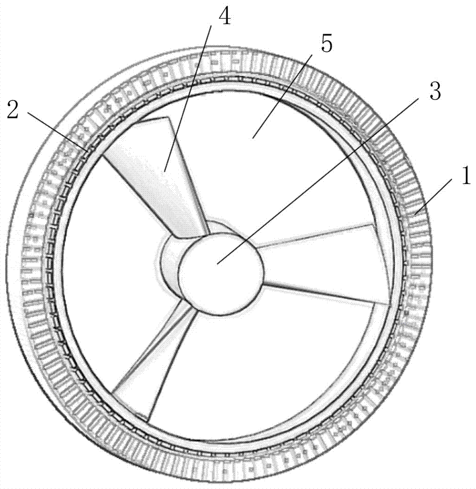
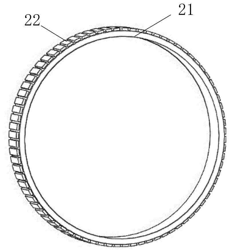
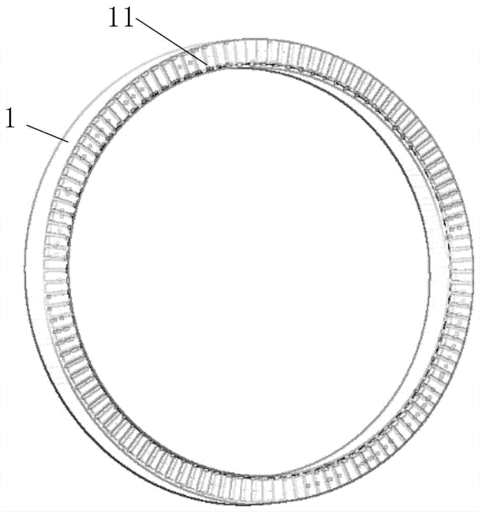
[0030] see Figure 1-4As shown, the present invention relates to a distributed flow energy power generation device, including a generator stator and a generator rotor, the generator rotor rotates relative to the generator stator, and the generator rotor includes a ring-shaped rotor body , the center of the inner circumference of the annular rotor body is provided with a central guide body concentric with it, and the circumference of the central guide body is evenly distributed with several blades, and the outer edge of the blade is connected with the inner wall of the annular rotor body. The connection between the blade and the inner wall of the annular rotor body is a flexible connection, and the flexible connection can use a U-shaped connection structure to connect the blade with the inner wall of the annular rotor body. The U-shaped connection structure can be understood as an elastic connection, which plays the role of shock absorption and mitigation, and can effectively r...


PUM


Abstract

The invention relates to a d istributed fluid energy-based electric power generation device comprising an electric power generator stator, an electric power generator rotor and blades; the electric power generator rotor comprises an annular rotor body, a central flow guiding body is arranged at a center of an inner circumference of the annular rotor body in a concentric manner, a circumference of the central flow guiding body is uniformly provided with a number of blades, and outer rims of the blades are connected with an inner wall of the annular rotor body; a number of axial direction fluid passage fluid flow channels are formed via respective enclosures of the blades and the central flow guiding body and the inner wall of the annular rotor body. According to a conventional electric power generator structure, fluid kinetic energy can be transmitted to an electric power generator only via arrangement of a transmission mechanism between an impeller and the electric power generator or arrangement of a speedup device; the annular rotor body can be directly driven to rotate via the blades of the electric power generation device disclosed in the invention, intermediate transmission links are eliminated, energy conversion efficiency is greatly improved, the electric power generator rotor is arranged on tail ends of fluid energy receiving blades, relative movement between a permanent magnet and a wire coil is effectively amplified, and mechanical energy consumption caused via arrangement of a speedup mechanism can be reduced by times.

Description

technical field [0001] The invention relates to the field of generator devices, in particular to a distributed current energy generating device. Background technique [0002] Since 2004, successive blackouts in the United States, Canada, the United Kingdom, Australia, Denmark, Sweden, Italy and other countries have profoundly demonstrated that there are serious technical defects in traditional energy supply forms. With the development of the times, especially the information society It is highly developed, and the traditional power supply form is no longer able to continue to support the development of human civilization. It is necessary to accelerate the establishment of a new energy system in the information age, and distributed energy will surely become the core technology of this system. [0003] Distributed energy is an energy development method that can best reflect multiple advantages such as energy saving, emission reduction, safety, and flexibility. China has a lar...

Claims


Application Information

Patent Timeline
IPC IPC(8): H02K7/18F03D9/00F03D1/06F03B13/00F03B3/12
CPCF03B3/121F03B13/00F03D1/0675F05B2220/706H02K7/1823Y02E10/20Y02E10/72
Inventor 耿天侃
Owner 耿天侃
Why Eureka
Try Eureka