Treatment system for nitrogen and phosphorus nutritive salt polluted bottom mud

A technology of polluted bottom sludge and treatment system, which is applied in the directions of sludge treatment, water/sludge/sewage treatment, fixed/solidified sludge treatment, etc. To solve the problems of less reserved land, achieve the effect of high degree of intensification, speed up coagulation efficiency, and reduce mechanical energy consumption

Pending Publication Date: 2020-01-17
汕头市弘东环境治理有限公司
View PDF0 Cites 1 Cited by
  • Summary
  • Abstract
  • Description
  • Claims
  • Application Information

AI Technical Summary

Problems solved by technology

Among them, the in-situ treatment technology mainly uses dredging equipment to backfill the polluted sediment to the shore, and adds a curing agent to dehydrate and solidify to form a revetment, so as to realize the reduction, harmlessness and resource utilization of the polluted sediment. Due to the hydrological conditions of the river itself, the silt generated cannot be effectively treated in some areas where the river channel is narrow or it is difficult to build a revetment; the ex-situ treatment technologies mainly include leaching, vitrification, electric repair, incineration, etc. The current problems are mainly application The cost is high, and there is a certain market in developed countries, but it has not been popularized in our country. However, due to the shortage of land in most places, and the huge amount of dredging works in general rivers, the vacant land that can be backfilled is relatively large. Less, and more affected by transportation costs

Method used


Image

  • Treatment system for nitrogen and phosphorus nutritive salt polluted bottom mud
  • Treatment system for nitrogen and phosphorus nutritive salt polluted bottom mud

Examples


Embodiment Construction

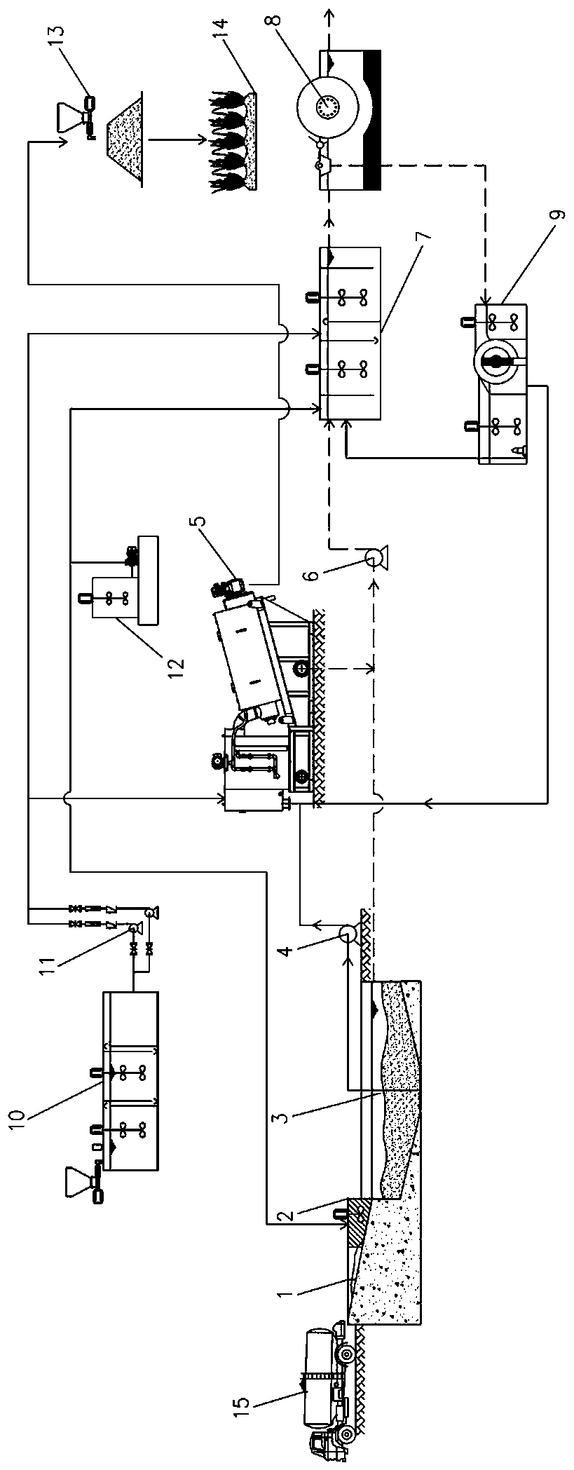
[0018] see figure 1 , figure 2 As shown, it is a structural schematic diagram of a preferred embodiment of the present invention. The present invention is a treatment system for nitrogen, phosphorus, and nutrient salt-contaminated sediments. It is aimed at dredging areas such as rivers, lakes, culverts, and box culverts. The boat or self-priming pump truck uses a powerful suction pump for suction. The sludge pumped out is mainly the surface layer and suspended layer of sediment rich in pollutants. The soil quality is mostly fluid and plastic with a high moisture content. After the bottom sludge is tested, the sludge bottom sludge rich in organic matter and nitrogen and phosphorus nutrients is treated as follows:

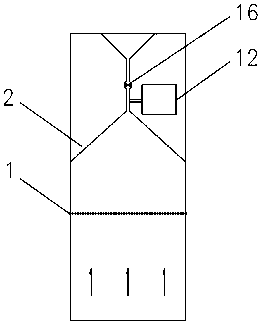
[0019] The sludge produced by dredging is transported to the treatment site by self-priming pump truck 15, and the sludge first passes through the pretreatment area. The pretreatment area includes a grid 2, an operating platform 2 and a sludge adjustment tank 3. Th...


PUM


Abstract

The invention provides a treatment system for nitrogen and phosphorus nutritive salt polluted bottom mud. The treatment system mainly comprises a pretreatment area for treating sludge, a PAM automaticdosing device which is used for respectively supplying chemicals to the front end of the stacked spiral sludge dewatering machine and the coagulation reactor; a PAC dosing device which is used for respectively supplying chemicals to the pretreatment area and the coagulation reactor. A treatment method comprises following steps: sludge is treated in the pretreatment area, is conveyed to a stackedspiral sludge dewatering machine through a sludge lifting pump, is mixed and contacted with PAM medicine powder at the front end of the stacked spiral sludge dewatering machine and then dewatered to form a sludge cake; a filtrate obtained in the pretreatment area and a sludge filtrate obtained in the stacked spiral sludge dewatering machine are conveyed into the coagulation reactor through a filtrate lifting pump; a mixed liquid from the coagulation reactor is conveyed into magnetic separation equipment to complete slag-liquid separation, then waste slag is introduced into a magnetic recoverydevice to achieve separation of magnetic seeds and non-magnetic seeds, and the non-magnetic seeds are conveyed into the stacked spiral sludge dewatering machine again. Treatment of polluted bottom mudand rapid nitrogen and phosphorus removal are achieved, the sludge treatment cost is effectively reduced, and secondary pollution is avoided.

Description

technical field [0001] The invention relates to technologies such as disposal of contaminated bottom sludge and residual water treatment and discharge, and is mainly applied to the harmless, reduction and resourceful treatment of nitrogen, phosphorus, and nutrient-salt-contaminated bottom sludge. processing system. Background technique [0002] Sediment is an important part of river and lake water environment ecology. In many rural and township areas, due to factors such as unreasonable layout of drainage pipe networks, imperfect sewage interception pipelines, and slow construction of sewage plants, a lot of domestic sewage is directly discharged into surrounding rivers or lakes without treatment, resulting in poor water quality. The deterioration and the pollution of the bottom mud, together with the dead residues and excrement of various aquatic organisms are continuously deposited at the bottom, forming a huge endogenous pollution. Due to the continuous accumulation and...

Claims


Application Information

Patent Timeline
Patent Type & Authority Applications(China)
IPC IPC(8): C02F11/125C02F11/121C02F11/143C02F11/147C02F1/48C02F11/00
CPCC02F1/488C02F11/008C02F11/121C02F11/125C02F11/143C02F11/147C02F2103/007
Inventor 万由鹏林静伟王晓晓吴海奋张兆坤
Owner 汕头市弘东环境治理有限公司
Why Eureka
Try Eureka