A method of testing a proper functioning of a selective catalytic reduction system

A selective, correct technique for applications in chemical instruments and methods, separation methods, engine components, etc.

Inactive Publication Date: 2017-07-25
GM GLOBAL TECH OPERATIONS LLC
View PDF0 Cites 7 Cited by
  • Summary
  • Abstract
  • Description
  • Claims
  • Application Information

AI Technical Summary

Problems solved by technology

However, each functional test is only performed in the predetermined operating state of the internal combustion engine, so that the warning process can remain activated for a relatively long time after maintenance without providing any immediate evidence that the maintenance has been successful

Method used


Image

  • A method of testing a proper functioning of a selective catalytic reduction system
  • A method of testing a proper functioning of a selective catalytic reduction system
  • A method of testing a proper functioning of a selective catalytic reduction system

Examples


Embodiment Construction

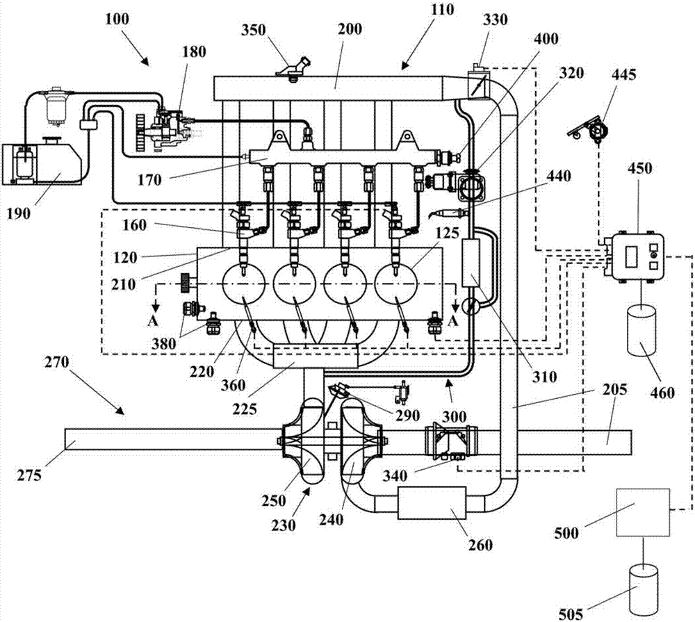
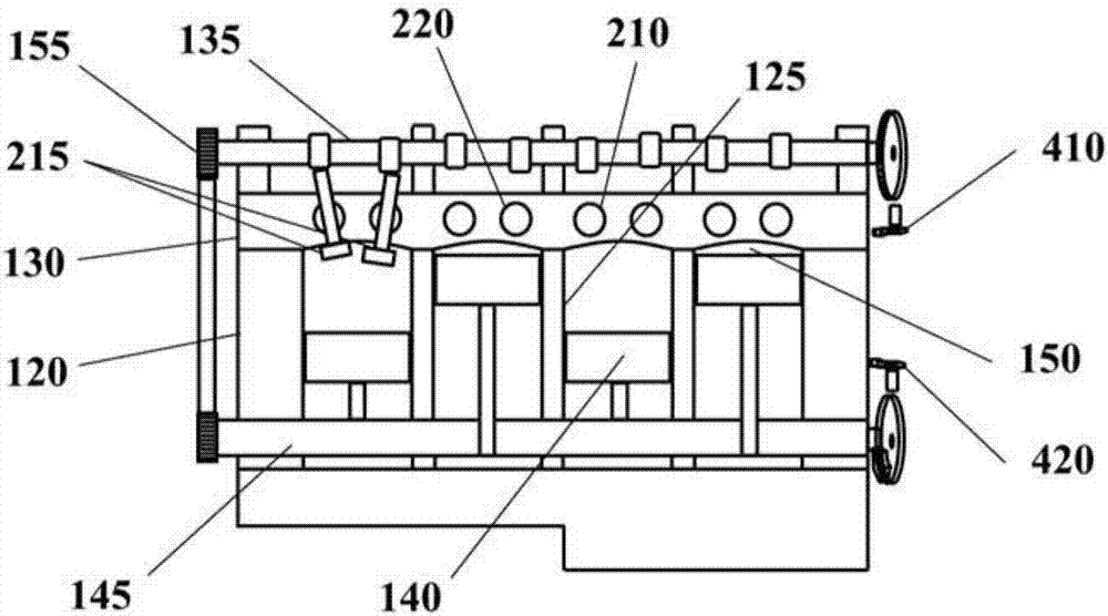
[0118] Some embodiments may include a motor vehicle (eg, a passenger car) implemented as the automotive system 100, such as figure 1 with 2 shown. The automotive system 100 includes an internal combustion engine (ICE) 110 having an engine block 120 defining at least one cylinder 125 having a piston 140 coupled to rotate a crankshaft 145 . Cylinder head 130 cooperates with piston 140 to define combustion chamber 150 . A fuel and air mixture (not shown) is disposed in combustion chamber 150 and ignited, the resulting thermally expanding exhaust causes reciprocating motion of piston 140 . Fuel is provided through at least one fuel injector 160 and air is provided through at least one inlet port 210 . Fuel injector 160 is provided fuel at high pressure from fuel rail 170 in fluid communication with high pressure fuel pump 180 which increases the pressure of fuel received from fuel source 190 . Cylinders 125 each have at least two valves 215 actuated by camshaft 135 , which rot...


PUM


Abstract

A method is disclosed to test for a proper functioning of a selective catalytic reduction system of an internal combustion engine. A selective catalytic reduction system includes a catalyst disposed in an exhaust pipe of the engine, an injector disposed in the exhaust pipe upstream of the catalyst for injecting a reducing agent, a pump for providing the reducing agent from a tank to the injector via a supply conduit and a pressure sensor for measuring a pressure within the supply conduit. The engine is operated at idle speed and a functionality check of the pressure sensor is executed. The engine is operated to increase an exhaust gas temperature in the exhaust pipe upstream of the catalyst and a functionality check of the pump is executed. A functionality check of the injector is executed after the functionality check of the pump and once the exhaust gas temperature has reached a predetermined target value thereof. A functionality check of the supply conduit is executed after the functionality check of the injector. The selective catalytic reduction system is identified as functioning properly when all of the functionality checks yields a positive result or malfunctioning when any one of the functionality checks yields a negative result.

Description

technical field [0001] The present invention relates to a method of testing the correct functioning of a selective catalytic reduction (SCR) system of an internal combustion engine, in particular an internal combustion engine of a motor vehicle (eg a gasoline engine or a diesel engine). Background technique [0002] SCR systems are known as aftertreatment devices designed to reduce nitrogen oxides (NOx) emitted by an internal combustion engine. The SCR system includes a catalyst that is placed in the engine's exhaust pipe to convert nitrogen oxides into natural nitrogen and water with the aid of a reducing agent. The reducing agent can be injected in liquid state to the exhaust pipe by a dedicated injector arranged upstream of the catalyst. The injector receives reductant from the tank through a pump that is in fluid communication with the injector via a supply conduit. [0003] The SCR system may also include a pressure sensor for measuring the pressure of the reductant i...

Claims


Application Information

Patent Timeline
Patent Type & Authority Applications(China)
IPC IPC(8): F01N11/00F01N3/28F01N3/20
CPCF01N3/208F01N3/28F01N11/00F01N2900/1808F01N2560/08F01N2610/1453F01N2610/14F01N2610/1433F01N2900/1404F01N2610/02B01D53/9431B01D53/9495B01D2251/2067F01N2550/05Y02T10/12Y02T10/40B01D53/9418F01N3/0814F01N3/2066F01N11/007F01N2550/02F01N2550/22F01N2570/14F01N2900/0416F01N2900/1402F01N2900/1822
Inventor A.乔尔达诺L.D.古尔雷洛克鲁兹M.诺塞雷托
Owner GM GLOBAL TECH OPERATIONS LLC
Why Eureka
Try Eureka