Integrated wind speed and direction measurement device and method for windmill cabin

A technology of wind speed, wind direction and measuring device, which is applied in measuring device, fluid speed measurement, speed/acceleration/impact measurement, etc. It can solve the problems of different signals, reduced accuracy and life, and reduced sampling frequency, etc., and achieves high data sampling rate , high service life and strong versatility

Active Publication Date: 2017-07-25
HUANENG CLEAN ENERGY RES INST +1
View PDF8 Cites 14 Cited by
  • Summary
  • Abstract
  • Description
  • Claims
  • Application Information

AI Technical Summary

Problems solved by technology

The piezoelectric wind measuring device can accurately measure the wind speed, but cannot directly detect the wind direction
Patent publication numbers CN201540301U and CN203720197U, in order to cooperate with wind measurement, mechanical parts are used, the accuracy and life are reduced, and these two patents cannot measure wind direction
Patent Publication No. CN104535790A, although the wind direction can be measured by twisting the vertical rod, but due to the introduction of mechanical parts, the sampling frequency is reduced and it is easily affected by icing
A common shortcoming of the above piezoelectric material wind measurement inventions is that the device is not specially developed for the wind turbine nacelle, so it cannot or can only be installed at the tail of the nacelle. wind speed
At the same time, another common deficiency of the above-mentioned piezoelectric material wind measurement invention is that it lacks temperature and atmospheric pressure sensors, and does not correct the air density. Under different atmospheric pressure and temperature conditions, the air density is different, so the same The signal generated by the wind speed is also different
[0005] In addition to the above-mentioned respective shortcomings, all the above-mentioned devices have the problem of being unable to self-check, that is, the device and the SCADA monitoring system cannot judge whether the wind measuring device itself has occurred measurement deviation and measurement error, and it is necessary to periodically check the wind measuring device through special equipment. Check the device

Method used


Image

  • Integrated wind speed and direction measurement device and method for windmill cabin
  • Integrated wind speed and direction measurement device and method for windmill cabin
  • Integrated wind speed and direction measurement device and method for windmill cabin

Examples


Embodiment 1

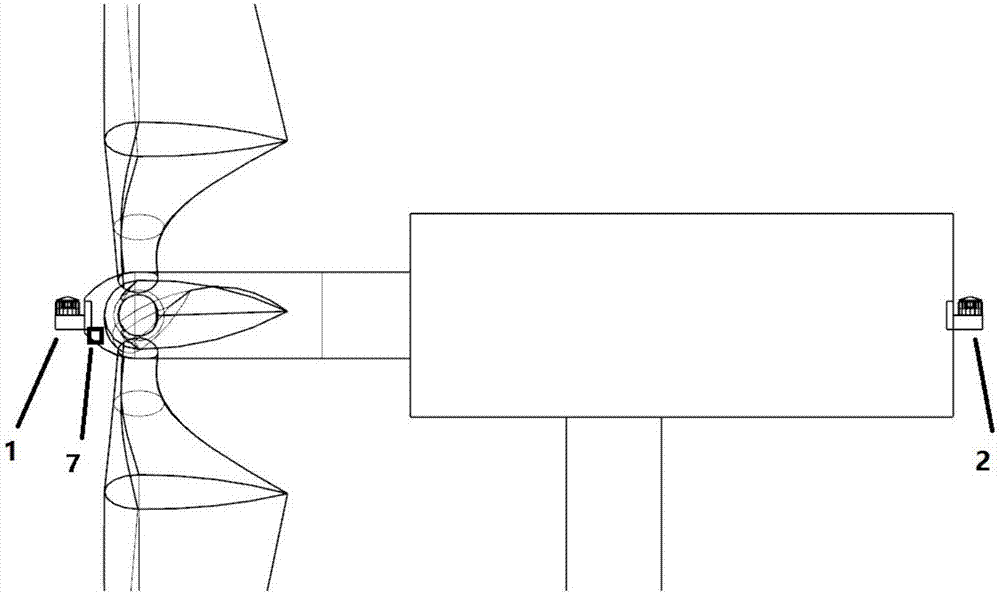
[0030] Embodiment 1: as figure 1 Shown is the overall layout of the wind turbine nacelle integrated wind speed and direction measuring device of the present invention. The installation process of the device is mainly as follows:

[0031] 1) Installation of wind measurement group 1 at the front edge of the hub. A hole is made at the center of the hub of the wind turbine nacelle, and the diameter of the hole is larger than the disc base 8, and the specific size depends on the required radial bearing. The center of the hole needs to be strictly aligned with the center of rotation of the hub. The roughness of the mating surfaces between the disc base 8 and the radial bearing is required to be above 3.2-6.3 μm. The anemometer group at the front edge of the hub is a fixed part and does not rotate with the hub of the cabin.

[0032] 2) Installation of wind measuring group 2 at the tail of the nacelle. A hole is opened in the middle of the tail plane of the wind turbine nacelle, ...

Embodiment 4

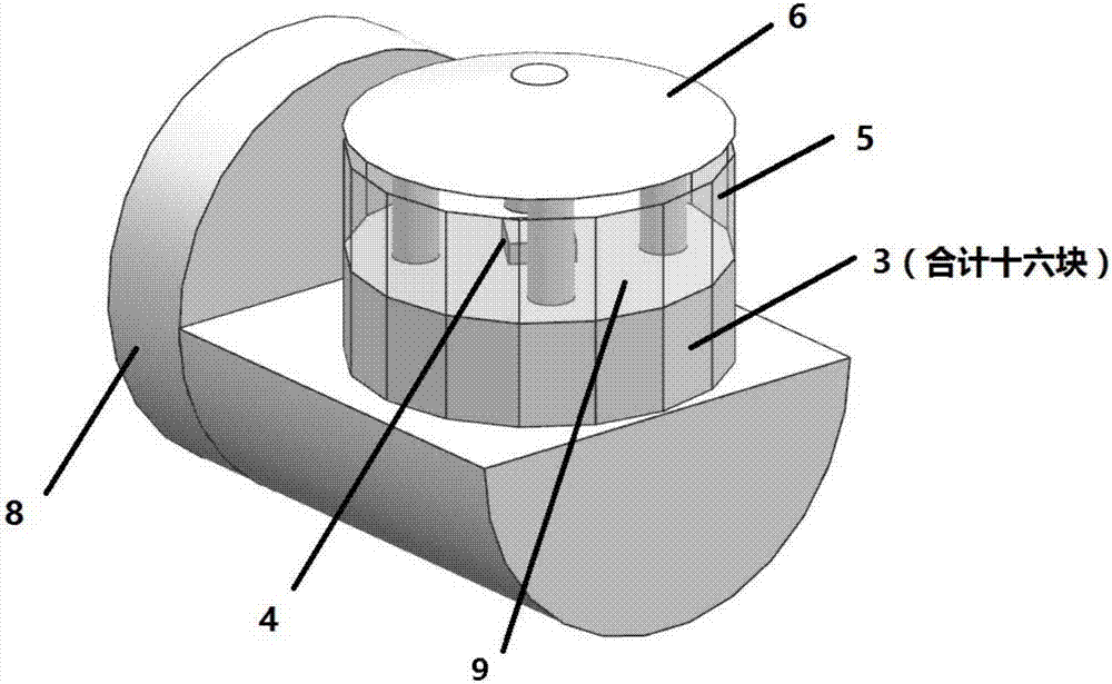
[0034]The relationship between embodiment 4 and embodiment 2 and embodiment 3 is the relationship between the whole and the part: the wind turbine nacelle integrated wind speed and direction measurement device firstly uses each velocity component measurement substrate 3 in embodiment 2 to measure and obtain the The magnitude of the wind pressure corresponding to the normal direction of the plate, and obtain the corresponding atmospheric pressure and temperature at this time through the embodiment 3, and finally according to the embodiment 4, the data of the embodiments 2 and 3 are analyzed and merged into the final vector wind speed. The specific steps of each embodiment are as follows.

Embodiment 2

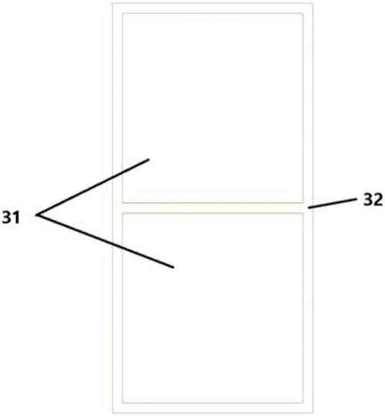
[0035] Example 2: Figure 3a and Figure 3b Shown is a schematic structural view of the velocity component measurement substrate of the present invention. The principle of signal measurement and calibration for each substrate is as follows:

[0036] The quantity of the piezoelectric ceramic sheets 31 of the velocity component measurement substrate 3 is n (n is an even number):

[0037] 1) Collecting signals: the piezoelectric ceramic sheet 31 collects voltage signals, and the voltage signals are arranged as P1, ..., Pn in ascending order, and the unit is V;

[0038] 2) Signal transmission: the signals of P1,...,Pn are filtered and amplified by the integrated circuit 71, and transmitted to the processor 73 by the internal I / O bus 72;

[0039] 3) A single velocity component measures the signal self-inspection of the substrate 3 and judges which piezoelectric ceramic sheet 31 fails and needs to be shielded: the criterion for judging is whether the measurement error between the...


PUM


Abstract

The invention discloses an integrated wind speed and direction measurement device and method for a windmill cabin, and the device comprises a wheel hub front-edge wind measurement set, a cabin tail wind measurement set, and a control system. The wheel hub front-edge wind measurement set and the cabin tail wind measurement set are respectively used for measuring the speed and direction of incoming wind from a front half plane and a rear half plane of the windmill. The invention also discloses a measurement device of the device. The device has no mechanical part, is long in service life, is high in data sampling rate, collects the atmospheric temperature and pressure correction air density in real time, and can judge whether there is a wrong operation or a big error through automatic judgment.

Description

technical field [0001] The invention belongs to the technical field of wind power generation, and in particular relates to an integrated wind speed and direction measurement device and method for a wind turbine nacelle. Background technique [0002] The accurate measurement of wind direction and wind speed is the basis of wind power operation control. Due to the high uncertainty of wind energy, it is necessary to accurately and timely measure the wind speed and direction in order to control the power generation of the wind turbine so that it can follow the change of the wind speed to obtain the maximum power generation and reduce the cost. The machine is controlled accordingly. [0003] The wind cup anemometer is the most commonly used wind measuring instrument on the wind turbine, and records the wind speed through the speed. However, the wind cup anemometer must be used in combination with the wind vane to complete the wind direction measurement. Since both the wind cup...

Claims


Application Information

Patent Timeline
Patent Type & Authority Applications(China)
IPC IPC(8): G01P5/00G01P13/02
CPCG01P5/00G01P13/025Y02E10/72
Inventor 刘鑫闫姝张波史绍平陈新明秦晔穆延非
Owner HUANENG CLEAN ENERGY RES INST
Why Eureka
Try Eureka