Single-tube double-ended inversion isolated DC-DC boost converter

A boost converter, DC-DC technology, applied in the electrical field, can solve the problems of easy saturation of the magnetic core, low utilization of the magnetic core, unidirectional excitation, etc. Effect

Inactive Publication Date: 2017-07-25
QINGDAO UNIV
View PDF5 Cites 14 Cited by
  • Summary
  • Abstract
  • Description
  • Claims
  • Application Information

AI Technical Summary

Problems solved by technology

[0004] The traditional isolated DC-DC boost converter topology has five circuit forms: forward type, flyback type, half-bridge type, full-bridge type, and push-pull type. Among them, the structure of forward type and flyback type circuits is simple, Low cost and easy to control, but there are disadvantages such as one-way excitation of the transformer, easy saturation of the magnetic core, low utilization rate of the magnetic core, difficulty in increasing the power, and difficulty in realizing soft switching control; the two-way excitation of the transformer in the half-bridge and full-bridge circuits, The utilization rate of the magnetic core is high, the power can be increased, and soft switching control can also be realized, but there is a bias problem, and the upper and lower bridge arms are easy to pass through, the circuit control is relatively difficult, and the reliability is low; the transformer of the push-pull circuit is also bidirectional excitation , there is no straight-through problem of the upper and lower bridge arms, but there is a bias problem, and the transformer needs to be tapped, the design is difficult, and soft switching cannot be realized
In recent years, an active clamp flyback circuit topology has emerged, which adds an active clamp branch to the traditional flyback topology, and enables the main switch to achieve zero-voltage soft switching through the auxiliary switch. At the same time, the auxiliary switching tube also realizes zero-voltage switching, and there is no shoot-through problem. Compared with the traditional flyback topology, the efficiency is greatly improved. Direct excitation, the magnetic core is easy to saturate, the utilization rate of the magnetic core is low, and the power is difficult to increase, etc., and the auxiliary switch tube of the clamping branch is complementary to the main switch tube, and the conduction loss of the auxiliary switch tube is relatively large, which restricts the Further Popularization and Application of Topology

Method used


Image

  • Single-tube double-ended inversion isolated DC-DC boost converter
  • Single-tube double-ended inversion isolated DC-DC boost converter
  • Single-tube double-ended inversion isolated DC-DC boost converter

Examples


Embodiment

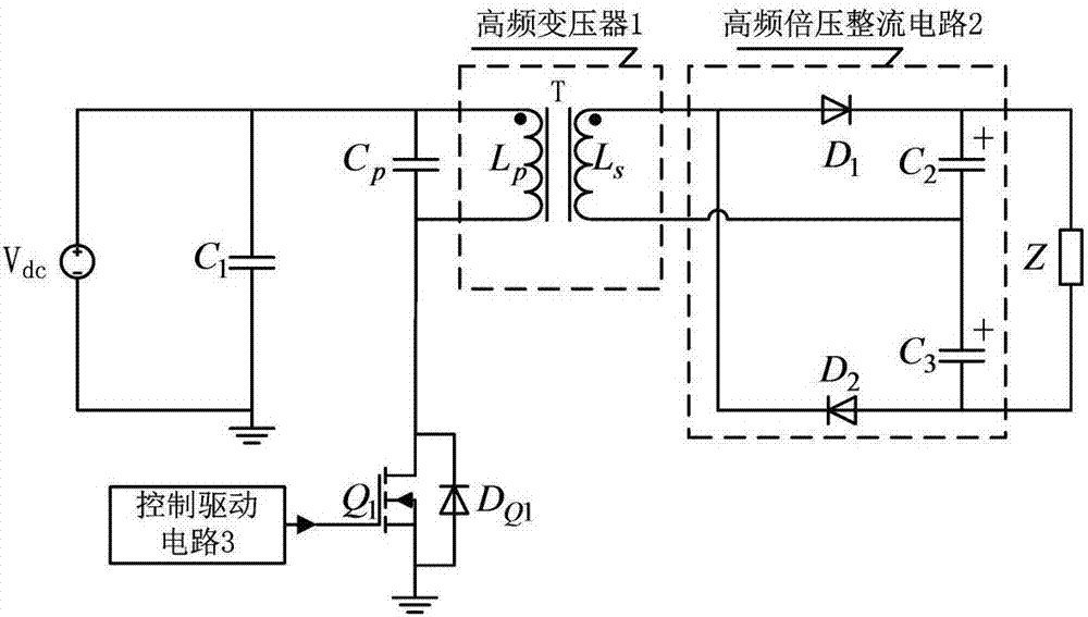
[0021] The main structure of the single-transistor double-terminal inverter isolation type DC-DC boost converter in this embodiment includes a first filter capacitor C 1 , Resonant capacitance C p , switch tube Q 1 , the first diode D Q1 , high-frequency transformer 1, high-frequency voltage doubler rectifier circuit 2, load Z and control drive circuit 3, V dc After the first filter capacitor C 1 After filtering, the switching tube Q 1 and the first diode D Q1 Invert the direct current into high-frequency alternating current, and the high-frequency alternating current is applied to the inductance L of the primary coil p Both ends of the secondary coil inductance L s The voltage is induced at both ends, and the secondary coil inductance L s The voltage at both ends is converted into direct current by the high-frequency voltage doubler rectifier circuit 2 to supply power for the load Z; the first filter capacitor C 1 For filtering, the resonant capacitor C p and primary...


PUM


Abstract

The invention belongs to the technical field of electrics and relates to a single-tube double-ended inversion isolated DC-DC boost converter. On the basis of a common single-ended flyback circuit topology, a resonant capacitor is connected in parallel with the primary side of a transformer, a high-frequency voltage-doubling rectifier circuit is connected in cascade with the secondary side of the transformer, the resonant capacitor in a parallel branch and a coil inductor in the primary side of transformer resonate so that an original converter is changed to two-way excitation, thereby improving magnetic core utilization rate, and improving output-to-input gain of an isolation converter; the high-frequency voltage-doubling rectifier circuit connected in cascade with the secondary side of the transformer enables the asymmetrical voltage output by the coil of the secondary side of the transformer to be effectively used so that the overall efficiency of the converter to is further improved.

Description

[0001] Technical field: [0002] The invention belongs to the field of electrical technology, and relates to a single-tube double-terminal inverter isolated DC-DC (direct current-direct current) boost converter, in particular to an isolated DC-DC with a single switch tube for double-terminal inverter Boost Converter Topology. [0003] Background technique: [0004] The traditional isolated DC-DC boost converter topology has five circuit forms: forward type, flyback type, half-bridge type, full-bridge type, and push-pull type. Among them, the structure of forward type and flyback type circuits is simple, Low cost and easy to control, but there are disadvantages such as one-way excitation of the transformer, easy saturation of the magnetic core, low utilization rate of the magnetic core, difficulty in increasing the power, and difficulty in realizing soft switching control; the two-way excitation of the transformer in the half-bridge and full-bridge circuits, The utilization rat...

Claims


Application Information

Patent Timeline
Patent Type & Authority Applications(China)
IPC IPC(8): H02M3/335H02M7/48
CPCH02M3/33523H02M7/48H02M7/4815Y02B70/10
Inventor 王春芳魏芝浩李震
Owner QINGDAO UNIV
Why Eureka
Try Eureka