Eureka AIR delivers breakthrough ideas for toughest innovation challenges, trusted by R&D personnel around the world.

Multi-power two-speed coupled speed variator

A technology of speed change device and multi-power, which is applied in the arrangement of multiple different prime movers of power device, pneumatic power device, and general power device, etc. It can solve the problem of complicated switching operation, difficult to withstand large torque, and low system reliability. problems, to achieve the effect of compact system structure, improved output power, and high operational reliability

Pending Publication Date: 2017-07-28
ZHUZHOU GEAR CO LTD
View PDF20 Cites 7 Cited by
  • Summary
  • Abstract
  • Description
  • Claims
  • Application Information

AI Technical Summary

Problems solved by technology

[0002] After years of development, the gasoline-electric hybrid coupling system has developed from the original discrete structure of the engine and electric motor to the modular integration of the engine, electric motor and transmission. The typical one in the existing technology is similar to Toyota THS (Toyota Hybrid System) For example, a hybrid power transmission device disclosed in Chinese patent 201610410620.1, its notable feature is the power transmission structure of the "shaft center shaft" (that is, a solid shaft is set inside the hollow shaft). On the other hand, the solid shaft is difficult to withstand high torque due to its small diameter. With the trend of motor miniaturization, high torque, and high speed, the disadvantages of this "shaft-in-shaft" power transmission structure are getting worse. more and more obvious
In addition, another feature of this solution is that the powertrains are coaxially arranged, the axial length is too long, the structure is complex, the system reliability is low, and more clutches and brakes are needed to realize pure electric, idling start-stop, driving Power generation, independent drive, hybrid drive, regenerative braking and other working modes, the switching operation of each working mode is complicated, and the number of gear sets passed by the transmission is large, and the transmission efficiency is low

Method used


Image

  • Multi-power two-speed coupled speed variator
  • Multi-power two-speed coupled speed variator
  • Multi-power two-speed coupled speed variator

Examples


Embodiment 1

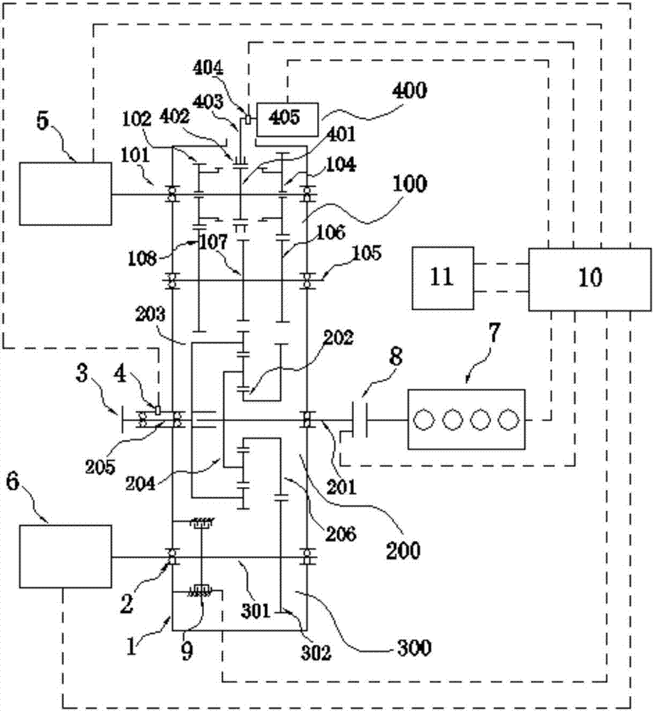
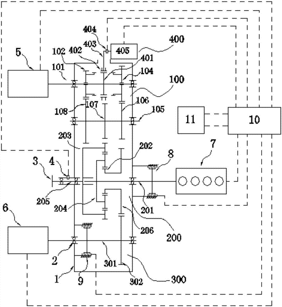
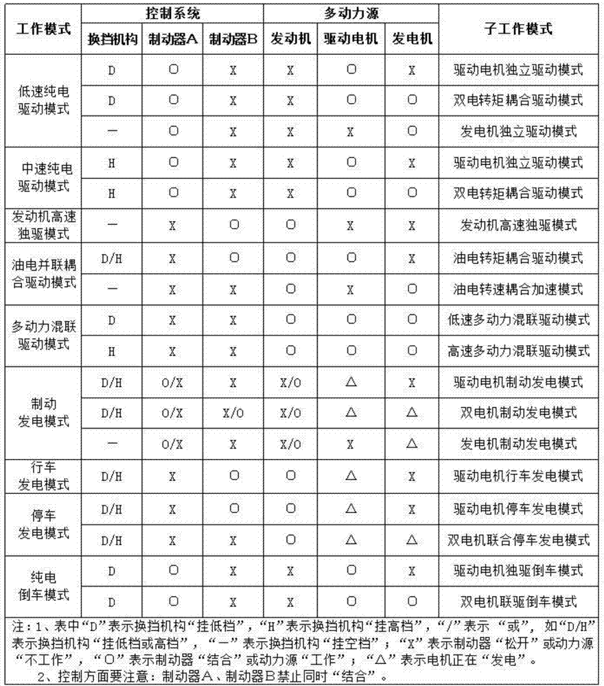
[0042] In the first embodiment, the brake A and the brake B both use hydraulic brakes, and the drive motor and the generator are both assembled motors that can both provide external power and generate electricity, that is, both the drive motor and the generator include a drive winding and a power generation winding. , and is connected with an energy storage element (the battery 11 in the first embodiment).

[0043] In the first embodiment, the axis lines of the input shaft 1, the input shaft 2, the input shaft 3 and the intermediate shaft are parallel to each other and not on the same straight line, and the input shaft 1, the input shaft 2, the input shaft 3 and the intermediate shaft are in the radial direction. Arranged in a row, thereby reducing the axial size of the transmission and making room for the arrangement of other assemblies.

[0044] In the first embodiment, the constant meshing gear is arranged at the position of the intermediate shaft corresponding to the engag...


PUM


Abstract

The invention provides a multi-power two-speed coupled speed variator. The multi-power two-speed coupled speed variator comprises a gear ring (203), a planet carrier (204) and a sun gear assembly arranged in the radial direction from outside to inside and engaged in sequence, the gear ring is provided with an internal tooth and an external tooth, the internal tooth is engaged with a planet wheel, the external tooth is engaged with a normally engaged gear (107), one end of a second input shaft is supported by the gear ring in a rotary mode, the other end of the second input shaft is connected with an engine (7) through a clutch device (8), the planet carrier is fixedly connected with the second input shaft, and the sun gear assembly comprises a sun gear (202) and a generator drive wheel (206) disposed integrally with the sun gear; one end of a third input shaft (301) is connected with a generator (6) through a brake B (9), and a generator driven wheel (302) engaged with the generator drive wheel is fixedly arranged on the third input shaft; and according to the multi-power two-speed coupled speed variator, multi-power coupling based on the large torque and the high rotation speed can be realized, the working mode is flexible and diverse, the structure is simple, the transmission efficiency is high, and the stability is good.

Description

technical field [0001] The invention relates to the technical field of gasoline-electric hybrid vehicles, in particular to a multi-power two-speed coupling transmission device for hybrid vehicles. Background technique [0002] After years of development, the oil-electric hybrid power coupling system has developed from the original discrete structure of the engine and the motor to the modular integration of the engine, the motor and the transmission. The typical one in the existing technology is similar to the Toyota THS (Toyota Hybrid System). For example, a hybrid power transmission device disclosed in Chinese Patent No. 201610410620.1 is characterized by a power transmission structure of "shaft center shaft" (that is, a solid shaft is set in the hollow shaft). On the other hand, the solid shaft is difficult to withstand high torque due to its small diameter. With the trend of miniaturization, high torque and high speed of the motor, the disadvantages of this "shaft-in-shaf...

Claims


Application Information

Patent Timeline
IPC IPC(8): B60K6/365B60K6/40B60K6/547
CPCB60K6/365B60K6/40B60K6/547Y02T10/92Y02T10/62
Inventor 王国良田联明肖育波
Owner ZHUZHOU GEAR CO LTD
Why Eureka
Eureka Blog
Learn More