Tail gas after-treatment pipeline system for internal combustion engineering machinery

A technology for exhaust after-treatment and pipeline system, applied in exhaust treatment, mechanical equipment, exhaust devices, etc., can solve the problems of substandard emission, heating failure of urea tank, wear and tear, etc., to ensure reliability, easy connection and maintenance effect

Pending Publication Date: 2017-07-28
ANHUI HELI CO LTD
View PDF5 Cites 2 Cited by
  • Summary
  • Abstract
  • Description
  • Claims
  • Application Information

AI Technical Summary

Problems solved by technology

Due to the mechanical failure of the solenoid valve in water heating, such as wear and tear, it may cause the heating failure of the urea tank. Th

Method used


Image

  • Tail gas after-treatment pipeline system for internal combustion engineering machinery
  • Tail gas after-treatment pipeline system for internal combustion engineering machinery
  • Tail gas after-treatment pipeline system for internal combustion engineering machinery

Examples


Embodiment

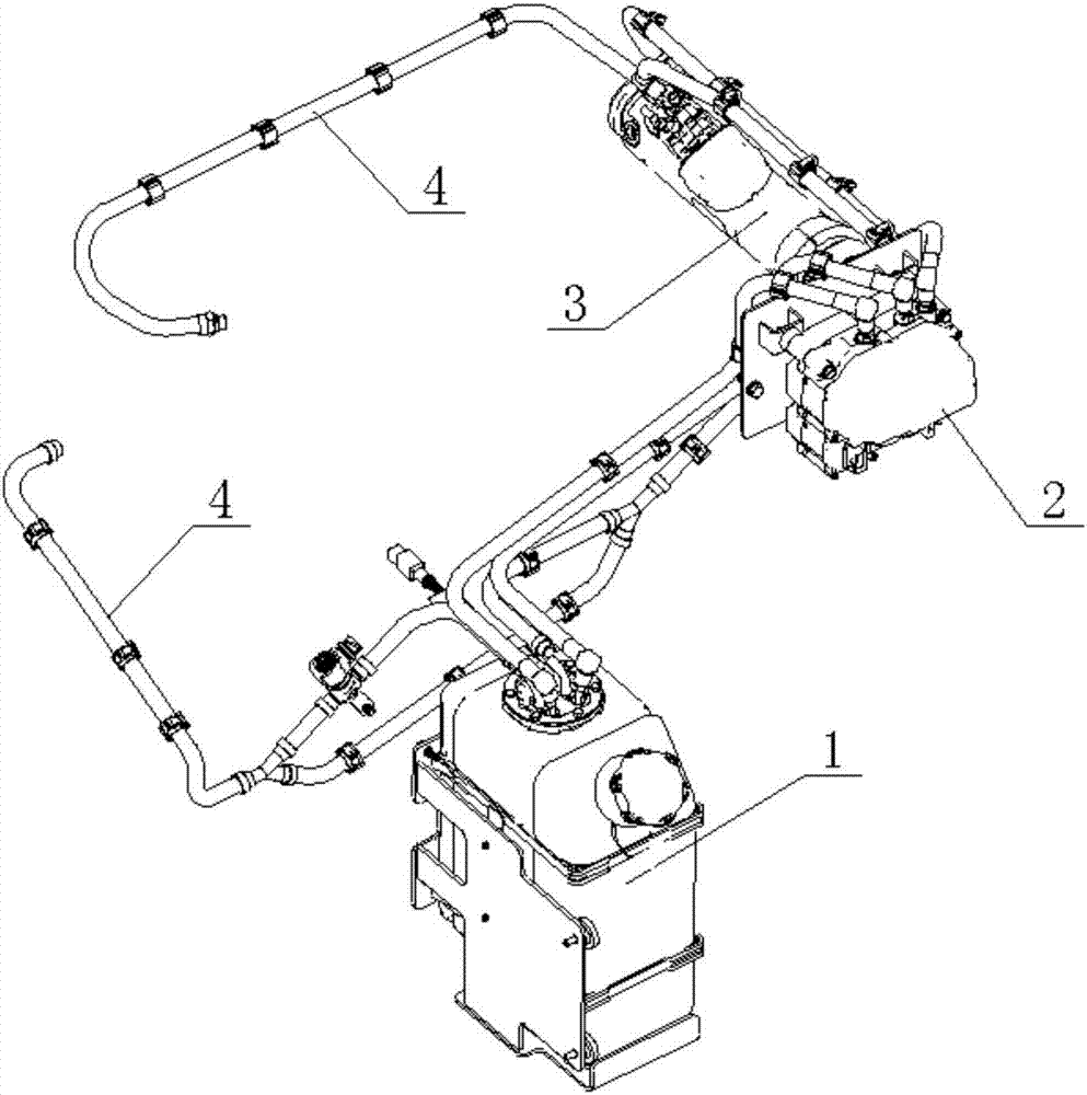
[0034] see figure 1 , an internal combustion engineering machinery exhaust gas post-treatment pipeline system, including a urea tank 1, a urea pump 2, a DRT pipe 3 and a cooling water pipeline 4.

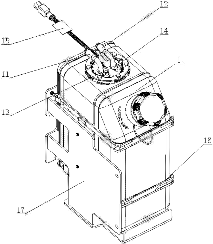
[0035] see figure 2 , the top of the urea tank 1 is provided with a pipeline integration cover, and the pipeline integration cover is provided with a water inlet interface 11, a water outlet interface 12, a urea suction interface 13, a urea return interface 14, and a temperature and urea level sensor 15. The water inlet port 11 , the water outlet port 12 are connected through the circulating cooling water path in the urea tank 1 . The urea suction interface 13 , the urea return interface 14 are connected through the inlet and outlet of the urea pump 2 . The temperature and urea liquid level sensor 15 senses the temperature signal of urea in the urea tank 1 and sends the temperature signal to the temperature control solenoid valve 49 . The urea tank 1 is provided with a hoop 16 a...


PUM


Abstract

The invention discloses a tail gas after-treatment pipeline system for internal combustion engineering machinery. A main water inlet pipe is arranged at the front end of the pipeline system, one end of the main water inlet pipe is connected with an internal combustion engine cooling water pipeline in a communicating manner, warm water in the internal combustion engine cooling water pipeline is delivered into a urea box, and urea in the urea box is heated in a circulating manner; and meanwhile, the warm water in the internal combustion engine cooling water pipeline is delivered into a DRT pipe, and a urea injection device in the DRT pipe 3 located in an internal combustion engine high-temperature exhaust system is cooled. The back end of a cooling water pipeline communicates with a water return pipeline of the internal combustion engine cooling water pipeline from a water outlet of the DRT pipe, and a closed-loop circulation system of the cooling water pipeline is formed. With the system, the reliability of a tail gas treatment device for the internal combustion engineering machinery is improved, a urea solution for chemical reactions can be timely and effectively supplied to an after-treatment device, and thus exhausted tail gas can meet the standard requirements. According to the system, pipelines are arranged clearly and are connected reliably, and mounting and dismounting are easy.

Description

technical field [0001] The invention belongs to the field of internal-combustion engineering machinery, and in particular relates to an exhaust gas post-treatment pipeline system of internal-combustion engineering machinery. Background technique [0002] In order to control the nitrogen oxides in the exhaust gas, most internal combustion engine manufacturers adopt the SCR technology route, in which the SCR equipment is used for the reduction reaction of the gas mixed with the nitrogen oxides and urea solution under the action of the catalyst to convert it into nitrogen and water. [0003] Due to the crystallization of urea solution in a low temperature environment, the pipeline will be blocked, resulting in the inability of the urea pump to effectively provide urea solution for chemical reactions, resulting in substandard emissions; and the injection device of the DRT pipe for urea solution is connected in series in the exhaust pipeline system Among them, its temperature is ...

Claims


Application Information

Patent Timeline
IPC IPC(8): F01N3/20F01P7/14
CPCF01N3/2066F01P7/14F01P2007/146F01N2610/1486F01N2610/02F01N2610/14
Inventor 徐庆华张祥江士同陈洋李少波王玲
Owner ANHUI HELI CO LTD
Why Eureka
Try Eureka