
Shadow ventilation engine

A technology of engine and engine block, which is applied in the direction of combustion engine, machine/engine, internal combustion piston engine, etc. It can solve the problems of restricting the development space of miniaturization of automobile displacement, short service life, and inability to fully utilize waste heat of exhaust gas, etc., and achieve the goal of overcoming Left and right shaking and side pressure wear, improving air tightness and service life, and improving the effect of energy saving and emission reduction

Active Publication Date: 2017-07-28
邵勇
View PDF4 Cites 0 Cited by
  • Summary
  • Abstract
  • Description
  • Claims
  • Application Information

AI Technical Summary

Problems solved by technology

[0002] At present, the most advanced automobile engine technology in the world still has many major defects due to the constraints of the traditional aerodynamic layout: (1), most of the existing engines use a single four-stroke working mode to meet environmental protection emission requirements, and cannot achieve two The high-efficiency, energy-saving and environmentally-friendly working mode of the stroke directly leads to the inability to fully utilize the waste heat of the exhaust gas and low thermal efficiency; (2) the existing engine usually adopts an asymmetrical mechanical structure design, which leads to difficult mechanical balance, large wear of the piston, and low mechanical efficiency; (3) Most of the existing engines use turbocharging to realize the miniaturization of automobile displacement. The manufacturing cost of turbochargers is high and the service life is short. Torque output, thus seriously restricting the development space for the miniaturization of automobile displacement; (4) Existing engines mainly rely on external circulation to realize the utilization of exhaust gas, and need to load a special recycling device on the outside, which cannot realize the direct recovery of waste heat. Utilization, the engine type is usually classified and designed according to the fuel type, which cannot support new energy and generalize the design

Method used


Image

  • Shadow ventilation engine
  • Shadow ventilation engine
  • Shadow ventilation engine

Examples


Embodiment Construction

[0020] Below by embodiment and in conjunction with accompanying drawing, the present invention will be further described:

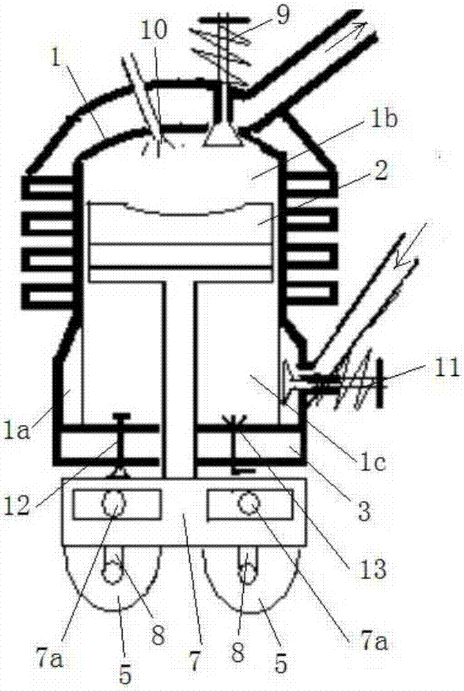
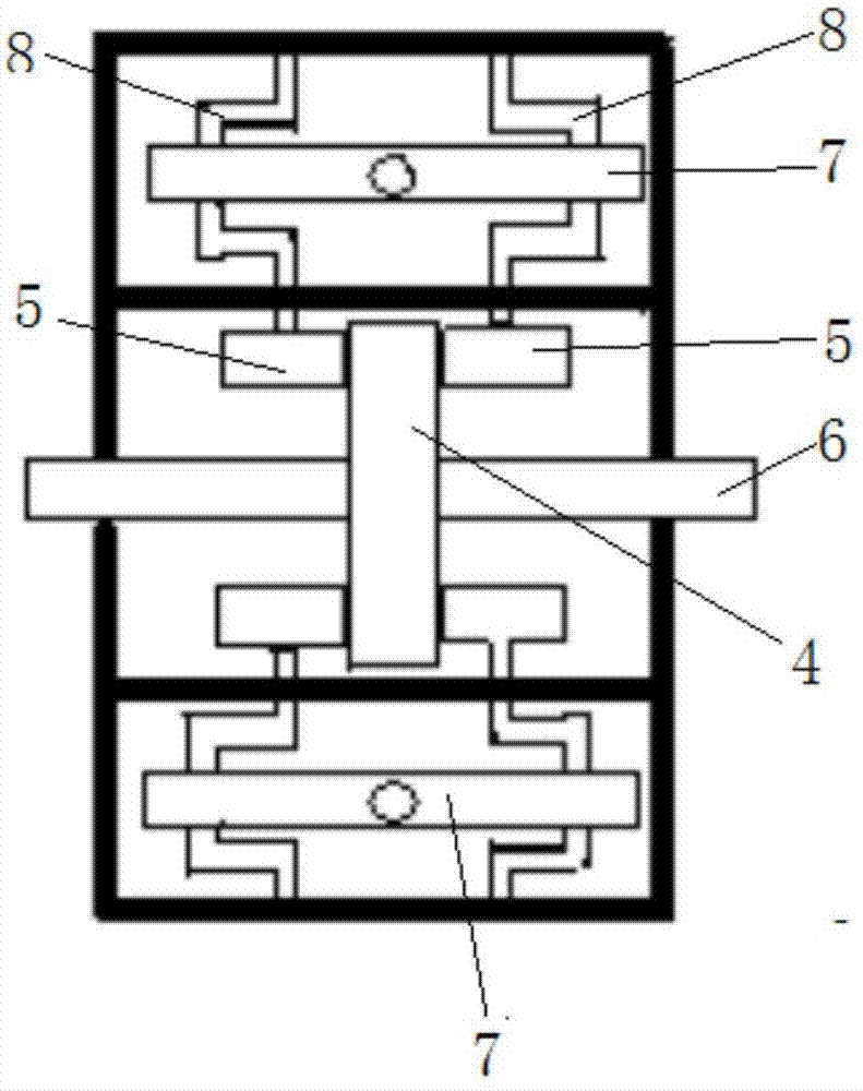
[0021] combine figure 1 — figure 2 Shown, a kind of shadow ventilation engine is mainly made up of engine block 1, block piston 2, cylinder head 3, power take-off gear 4, transmission gear flywheel 5, transmission shaft 6, T-shaped push-pull rod 7, short arm crankshaft 8 composition.

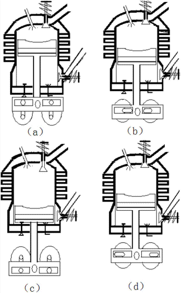
[0022] The top of the engine block 1 is provided with a fuel nozzle 10 and an exhaust valve 9 . The exhaust valve 9 is used to control the opening and closing of the exhaust hole of the engine block 1; fuel is injected into the engine block 1 through the fuel nozzle 10, such as the cylinder piston 2 moves up and down once, and the high-pressure gas is penetrated once, and the fuel nozzle 10 spray oil once, compression ignition works once, then the shadow ventilating engine is a two-stroke working mode; if the cylinder piston 2 moves up and down twice, high-pressure air ...


PUM


Abstract

The invention discloses a shadow ventilation engine. A fuel nozzle and an exhaust valve are arranged at the top of an engine cylinder; a gas penetration groove and an intake valve are arranged on the inner wall of the lower part of the engine cylinder; an oil return valve and a machine oil nozzle are arranged on a cylinder cover; a small end of a T-shaped push-pull rod penetrates through the cylinder cover and extends into the engine cylinder to connect with a cylinder piston; two sleeved strip-shaped holes are arranged at a large end of the T-shaped push-pull rod left and right at intervals, and are respectively connected with short arm crankshafts; the axis of each short arm crankshaft is sleeved with a transmission tooth flywheel; two transmission tooth flywheels are positioned on two sides of a power output gear, and are in engaged transmission with the power output gear; the two transmission tooth flywheels are driven by the cylinder piston to synchronously and oppositely rotate; and a transmission shaft is driven to rotate through an output gear. An upper cavity is a gas compression ignition acting area and a waste gas discharge area; a lower cavity is a natural gas sucking area and a high-pressure gas penetration area; two working areas synchronously work without influencing each other; and the high-efficiency internal recycling of waste gas and afterheat can be realized without needing external circulation and turbocharging.

Description

technical field [0001] The invention relates to the technical field of automobile engines, in particular to the aerodynamic layout design of the engine. Background technique [0002] At present, the most advanced automobile engine technology in the world still has many major defects due to the constraints of the traditional aerodynamic layout: (1), most of the existing engines use a single four-stroke working mode to meet environmental protection emission requirements, and cannot achieve two The high-efficiency, energy-saving and environmentally-friendly working mode of the stroke directly leads to the inability to fully utilize the waste heat of the exhaust gas and low thermal efficiency; (2) the existing engine usually adopts an asymmetrical mechanical structure design, which leads to difficult mechanical balance, large wear of the piston, and low mechanical efficiency; (3) Most of the existing engines use turbocharging to realize the miniaturization of automobile displace...

Claims


Application Information

Patent Timeline
Patent Type & Authority Applications(China)
IPC IPC(8): F02B67/04F02B69/06
CPCF02B67/04F02B69/06
Inventor 邵勇
Owner 邵勇
Learn More