
Pneumatic jet performance test bench

A technology of pneumatic jetting and test bench, applied in the testing of mechanical parts, testing of machine/structural parts, measuring devices, etc., to achieve the effect of improving the conveying distance, working stably, and being highly innovative.

Inactive Publication Date: 2017-07-28
CHINA UNIV OF MINING & TECH
View PDF6 Cites 1 Cited by
  • Summary
  • Abstract
  • Description
  • Claims
  • Application Information

AI Technical Summary

Problems solved by technology

However, so far, there are few injection performance test rigs for the structural characteristics of the injector.

Method used


Image

  • Pneumatic jet performance test bench
  • Pneumatic jet performance test bench
  • Pneumatic jet performance test bench

Examples


Embodiment Construction

[0027] Below in conjunction with accompanying drawing and specific embodiment, further illustrate the present invention, should be understood that these examples are only for illustrating the present invention and are not intended to limit the scope of the present invention, after having read the present invention, those skilled in the art will understand various aspects of the present invention All modifications of the valence form fall within the scope defined by the appended claims of the present application.

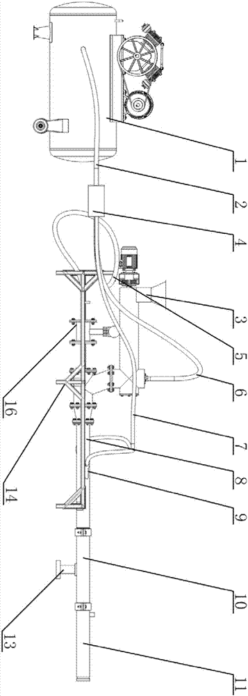
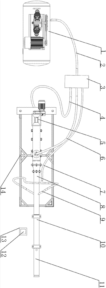
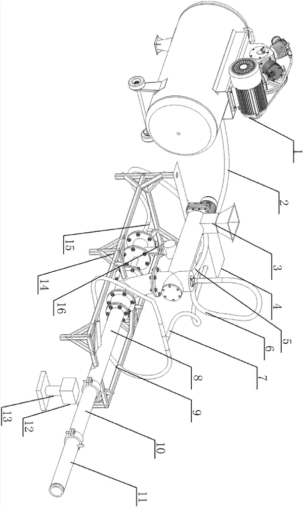
[0028] A kind of pneumatic injection performance test bench, is used for the performance test of pneumatic injector (8), such as Figures 1 to 3As shown, it includes air compressor (1), main air pipe (2), screw feeding device (3), proportional flow valve (4), main conveying air pipe (5), positive pressure air pipe (6), rotary Flow air pipe (7), swirl auxiliary pipe (9), transparent conveying pipe (10), conveying straight pipe (11), high-speed camera (12), steady flow...


PUM


Abstract

The invention discloses a pneumatic jet performance test bench comprising an air compressor (1), a main air duct (2), a spiral feeding device (3), a proportional flow valve (4), a main conveying duct (5), a positive pressure air duct (6), a swirl air duct (7), a pneumatic injector (8), a swirling auxiliary duct (9), a transparent conveying pipe (10), a straight conveying pipe (11), a high speed camera (12) , a camera stand (13), a support frame (14), an anemostat (15) and a vortex flowmeter (16). The test bench can use a multi-index orthogonal test scheme to study the influence rules of structural parameters of a pneumatic injector and the distribution ratio of different air flows on the jetting performance. By recording the pressure change of an internal flow field and the material transportation situation of an injection system under the combination of different parameters, the best injector parameters according with the actual working conditions are obtained, the efficiency of the pneumatic injector is improved, the reliability of a pneumatic conveying system is ensured, and pipe clogging and other accidents are reduced.

Description

technical field [0001] The invention relates to a pneumatic injection performance test bench, which is suitable for studying the influence rules of various structural parameters of the pneumatic injector and different air distribution ratios on the injection performance, and finding the optimal parameter range meeting the requirements of actual working conditions. Background technique [0002] When mining thin and extremely thin coal seams by drilling and mining, the post-mining filling protection of gobs by drilling and mining is the most ideal solution to solve roof collapse and reduce reserved coal pillars. However, the thin coal seam has a high gangue content, the mining height of the coal seam is small, and the working space of the filling face is limited. It is difficult for general filling equipment to enter the goaf. Effectively take into account the economic and environmental benefits of mining, improve the recovery rate of coal resources, and reduce filling costs. ...

Claims


Application Information

Patent Timeline
Patent Type & Authority Applications(China)
IPC IPC(8): G01M13/00
CPCG01M13/00
Inventor 李建平余柄辰王雁翔杨道龙周锋田世伟卜宇航段世杰
Owner CHINA UNIV OF MINING & TECH
Learn More