Preparation method of 3D ceramic backboard

A ceramic backplane, 3D technology, applied in ceramic molding machines, ceramic molding workshops, manufacturing tools, etc., can solve the problem that the utilization rate of powder is only about 10%, cannot process 3D ceramic backplanes, and there is no better processing method, etc. problem, achieve the effect of simple and efficient process route, reduce processing cost, and improve the utilization rate of powder

Active Publication Date: 2017-08-01
DONGGUAN XINBO STRUCTURAL CERAMICS CO LTD
View PDF7 Cites 5 Cited by
  • Summary
  • Abstract
  • Description
  • Claims
  • Application Information

AI Technical Summary

Problems solved by technology

The production process of the green body of ordinary ceramic casings is relatively simple. Basically, dry pressing and wet pressing of solid materials are used, and then processed into the required green body by CNC. This process uses a large amount of powder, low processing efficiency, and powder utilization. Only about 10%, resulting in high cost of producing ceramic backplanes and low processing yield, resulting in the failure of mass production of ceramic bodies
[0004] Furthermore, the grinding and polishing of the backplane adopts a single-sided and double-sided grinding and polishing machine for polishing. The single-sided and double-sided grinding and polishing machine is only suitable for grinding and polishing 2D and 2.5D ceramic backplanes. With the development of the market, the introduction of 3D ceramic backplanes, However, the single-side and double-side grinding and polishing machines cannot process 3D ceramic backplanes. The metal 3D back shell adopts an independent single-head and sponge polishing process, which is not suitable for polishing 3D ceramic backplanes.
There is no better way to deal with it

Method used


Image

  • Preparation method of 3D ceramic backboard
  • Preparation method of 3D ceramic backboard
  • Preparation method of 3D ceramic backboard

Examples


Embodiment Construction

[0030] In order to facilitate the understanding of the present invention, the following will describe the present invention more fully. However, the present invention can be embodied in many different forms and is not limited to the embodiments described herein. On the contrary, these embodiments are provided to make the understanding of the disclosure of the present invention more thorough and comprehensive.

[0031] Unless otherwise defined, all technical and scientific terms used herein have the same meaning as commonly understood by one of ordinary skill in the technical field of the invention. The terms used herein in the description of the present invention are for the purpose of describing specific embodiments only, and are not intended to limit the present invention.

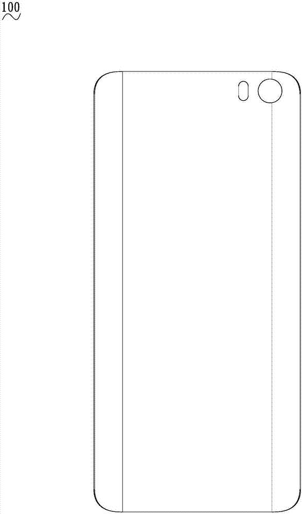
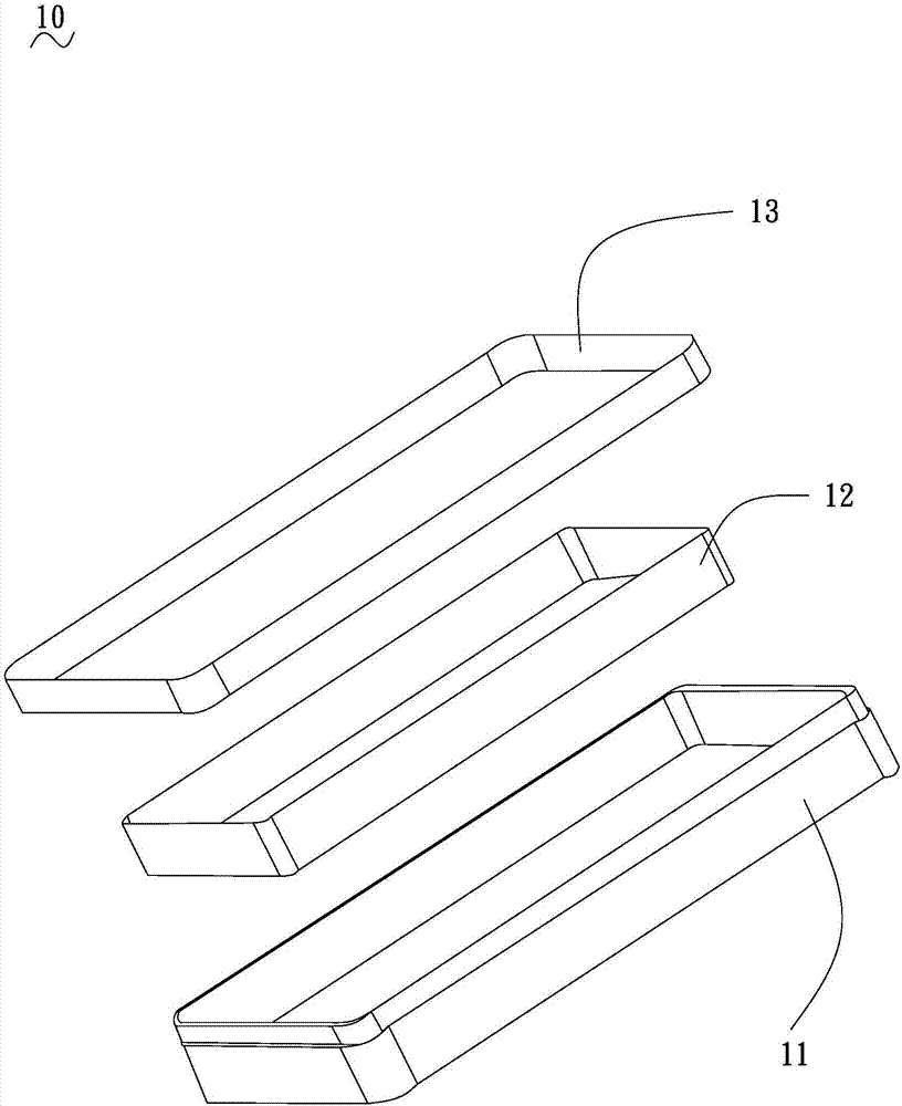
[0032] see figure 1 and 2 , is a 3D ceramic backplane 100 according to a preferred embodiment of the present invention, and the preparation method of the 3D ceramic backplane 100 includes the followin...


PUM


Abstract

The invention relates to a preparation method of a 3D ceramic backboard. The preparation method includes the following steps that ceramic powder is contained into a rubber die, the rubber die is sleeved with a plastic sleeve, and vacuumizing and preheating are carried out; the rubber die is placed into an isostatic pressing cylinder device to be pressed, and the rubber die is taken out after isostatic pressing is carried out; edge burrs are removed, and rubber discharging sintering is carried out; and a sweeping and polishing device is started to conduct polishing, and the 3D ceramic backboard is obtained. By means of the preparation method of the 3D ceramic backboard, a blank in a 3D shape can be directly molded, the powder using rate is improved by about 50%, meanwhile, the molding process is simple, and operation is easy; and the sweeping and polishing device is arranged, the one-face polishing function is used, a pure pig hair brush, a grinding rubber strip brush and the like are loaded on an upper die to be matched with drilling gypsum and polishing liquid to conduct the coarse sweeping process, the refined sweeping process and the like on the inwards-concave face and the peripheral side faces of the 3D ceramic backboard, the process route is simple and rapid, the effect is better, and the mirror surface effect is achieved.

Description

technical field [0001] The invention relates to the field of electronic product material manufacturing, in particular to a method for preparing a 3D ceramic back plate used for processing mobile phone shells. Background technique [0002] The mobile phone shell is not only the most direct way to protect the body, but also an important factor affecting its cooling effect, weight, and aesthetics. In view of the advantages of ceramic materials such as good touch, good corrosion resistance, not easy to age, and no electromagnetic shielding effect, they are more and more widely used in electronic products such as mobile phones and tablet computers. [0003] In the traditional technology, the ordinary ceramic backplane is a pure plane on the back of the backplane without any curved design; the 2.5D ceramic backplane is flat in the middle, but the edge is curved; and the 3D ceramic backplane, whether it is Both the middle and the edges are curved. The production process of the gr...

Claims


Application Information

Patent Timeline
Patent Type & Authority Applications(China)
IPC IPC(8): B28B1/00B28B15/00B28B3/00B28B11/18B28B11/24B24B29/02
CPCB24B29/02B28B1/001B28B3/003B28B11/18B28B11/243B28B15/00
Inventor 闫洪宾黄光荣王文利孙亮陈兰桂彭朝阳
Owner DONGGUAN XINBO STRUCTURAL CERAMICS CO LTD
Why Eureka
Try Eureka