
Drive-by-wire hydraulic braking and steering system

A technology of hydraulic braking and steering systems, applied in hydraulic braking transmissions, power steering mechanisms, electric steering mechanisms, etc., can solve the problems of unfavorable integrated control, large volume, poor stability, etc., and achieve high integration, Reduce volume and achieve precise control effect

Active Publication Date: 2017-08-01
JILIN UNIV
View PDF4 Cites 5 Cited by
  • Summary
  • Abstract
  • Description
  • Claims
  • Application Information

AI Technical Summary

Problems solved by technology

[0005] The technical problem to be solved by the present invention is to overcome the large volume occupied by the separate arrangement of the existing brake-by-wire system and the steering-by-wire system, the low integration, and the disadvantages of integrated control, as well as the existing brake-by-wire system and steering system. To solve the problem of poor stability of the steering-by-wire system when the system is powered off and fails, a steering-by-wire hydraulic brake steering system is provided

Method used


Image

  • Drive-by-wire hydraulic braking and steering system
  • Drive-by-wire hydraulic braking and steering system
  • Drive-by-wire hydraulic braking and steering system

Examples


Embodiment Construction

[0043] The present invention is described in detail below in conjunction with accompanying drawing:

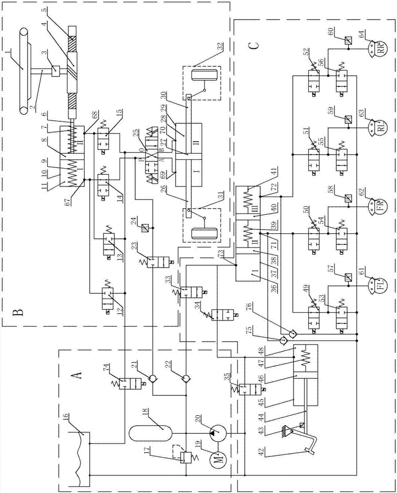
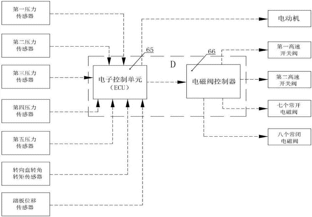
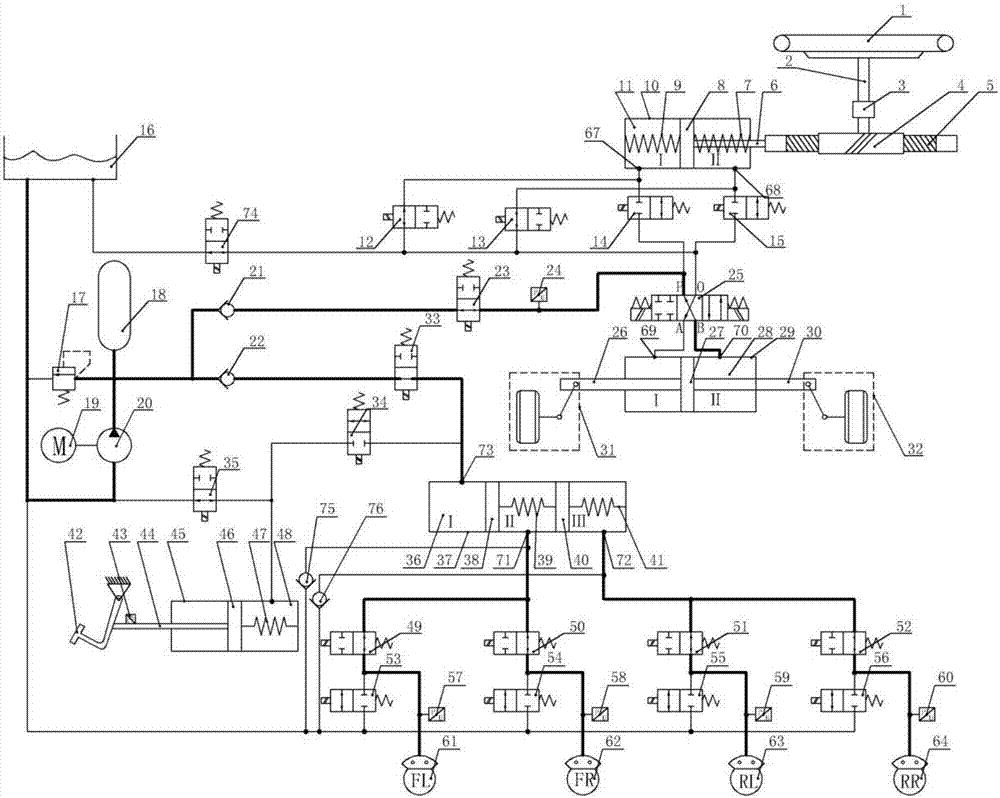
[0044] Such as figure 1 As shown, a hydraulic brake-by-wire steering system according to the present invention includes a hydraulic pressure source part A, a steering part B, a braking part C and an electric control part D.

[0045] The hydraulic pressure source part A includes an oil tank 16 , an overflow valve 17 , an accumulator 18 , an electric motor 19 , a hydraulic pump 20 , a first check valve 21 , a second check valve 22 and an eighth normally closed solenoid valve 74 .

[0046]The motor shaft of the motor 19 is connected to the input shaft end of the hydraulic pump 20 to ensure that the motor 19 can drive the hydraulic pump 20 to rotate, so that the hydraulic pump 20 can continuously output hydraulic oil to the hydraulic system through the oil outlet. The oil inlet of the hydraulic pump 20 is connected to the oil tank 16 through a hydraulic pipeline, so that the hydr...


PUM


Abstract

The invention discloses a drive-by-wire hydraulic braking and steering system. The drive-by-wire hydraulic braking and steering system solves the problems that an existing drive-by-wire braking and steering system arranged independently has a large occupied area and low integration and does not facilitate integrated control, and the existing drive-by-wire braking and steering system is poor in stability when the existing system does not work in case of power failure. The drive-by-wire hydraulic braking and steering system comprises a hydraulic source part, a steering part, a braking part and an electric control part; the hydraulic source part comprises a hydraulic pump, a first one-way valve, a second one-way valve and an eighth normally closed electromagnetic valve; the steering part comprises a first normally closed electromagnetic valve and a first high speed switching valve; the braking part comprises a second high speed switching valve and a seventh normally closed electromagnetic valve; the hydraulic source part is in pipeline connection with the steering part through the eighth normally closed electromagnetic valve, the first one-way valve, the first normally closed electromagnetic valve and the first high speed switching valve; the hydraulic source part is in pipeline connection with the braking part through the hydraulic pump, the second one-way valve, the second high speed switching valve and the seventh normally closed electromagnetic valve; and the power control part is in electric wire connection with the hydraulic source part, the steering part and the braking part.

Description

technical field [0001] The invention creates a steering device belonging to the technical field of automobile braking and steering systems. More specifically, the present invention relates to a hydraulic brake-by-wire steering system. Background technique [0002] Both the braking system and the steering system of a car are important components of a car's driving system. It is to control the driving direction of the car according to the driver's wishes. Initially, the braking system of automobiles used a vacuum booster device, which has the disadvantages of large volume, complex structure, high dependence on the engine, and inaccurate brake pressure control. Due to the above shortcomings, the current automotive industry has reduced the use of vacuum booster devices. use. The traditional automobile steering system is divided into mechanical steering system and power steering system. Only a small part of the energy required by the power steering system is provided by the dr...

Claims


Application Information

Patent Timeline
IPC IPC(8): B62D5/04B62D5/065B60T11/16B60T15/02
CPCB60T11/16B60T15/028B62D5/0403B62D5/065
Inventor 李静王晨刘鹏
Owner JILIN UNIV
Learn More