Supercharge Your Innovation With Domain-Expert AI Agents!

High voltage PMOS driving circuit

A driving circuit, high-voltage technology, applied in the field of high-voltage PMOS driving circuits, can solve the problems of power consumption, efficiency, frequency limitation, etc., and achieve the effect of reducing chip area, high conversion efficiency, and small switching loss

Active Publication Date: 2017-08-01
NORTH-CHINA INTEGRATED CIRCUIT CO LTD
View PDF12 Cites 2 Cited by
  • Summary
  • Abstract
  • Description
  • Claims
  • Application Information

AI Technical Summary

Problems solved by technology

However, since the source-gate voltage difference of high-voltage PMOS power transistors does not exceed 20V (the maximum does not exceed 30V), high-voltage PMOS power transistors can generally only be driven by discrete circuits, and power consumption, efficiency, and frequency are greatly affected. limit

Method used


Image

  • High voltage PMOS driving circuit
  • High voltage PMOS driving circuit
  • High voltage PMOS driving circuit

Examples


Embodiment Construction

[0016] The technical solutions in the embodiments of the present invention are clearly and completely described below in conjunction with the accompanying drawings in the embodiments of the present invention. Obviously, the described embodiments are only part of the embodiments of the present invention, not all of them. Based on the embodiments of the present invention, all other embodiments obtained by persons of ordinary skill in the art without making creative efforts belong to the protection scope of the present invention.

[0017] In the following description, a lot of specific details are set forth in order to fully understand the present invention, but the present invention can also be implemented in other ways different from those described here, and those skilled in the art can do it without departing from the meaning of the present invention. By analogy, the present invention is therefore not limited to the specific examples disclosed below.

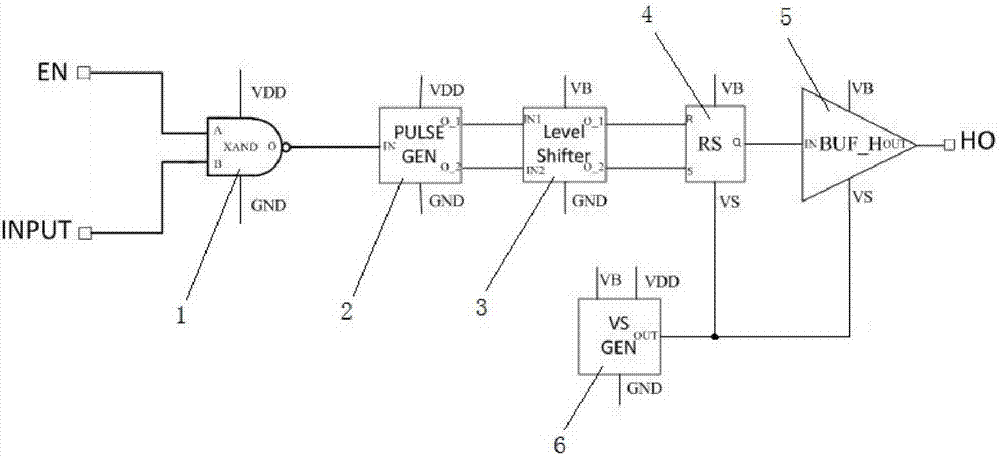
[0018] like figure 1 A...


PUM


Abstract

The invention discloses a high voltage PMOS driving circuit, and relates to the technical field of driving circuits of field effect transistors. The driving circuit comprises a NAND gate, a pulse signal generation circuit, a level shift circuit, a trigger, a buffer circuit and a VS voltage generation circuit, wherein an enable signal input end EN and a signal input port INPUT are respectively connected with two input ports A and B of the NAND gate, an output port O of the NAND gate is connected with an input port IN of the pulse signal generation circuit, two output ports O _1 and O _2 of the level shift circuit are respectively connected with two input ports of the trigger, the output port of the trigger is connected with the input port IN of the buffer circuit, and the output port OUT of the buffer circuit is connected with a driving voltage output port HO. The driving circuit has the advantages of simple structure, easy realization, small power consumption, small switching loss, high conversion efficiency, wide working voltage range, and no need for a bootstrap circuit.

Description

technical field [0001] The invention relates to the technical field of drive circuits applied to field effect transistors, in particular to a high-voltage PMOS drive circuit. Background technique [0002] The drive circuit amplifies the power of the low-voltage logic control signal to drive the power tube to work reliably. Power tubes are generally divided into PMOS power tubes and NMOS power tubes. The ultimate goal of driving circuit design is to make power switching devices work in close to ideal switching states, reduce switching losses, and improve overall system efficiency and reliability. Traditional driver circuits are used to drive NMOS power transistors. Compared with NMOS power transistors, driving PMOS power transistors has smaller switching losses. Moreover, driving the PMOS power tube does not require a bootstrap circuit (boost circuit) structure, and the power tube can be turned on and off for a longer period of time or even kept in the on state. It is very...

Claims


Application Information

Patent Timeline
Patent Type & Authority Applications(China)
IPC IPC(8): H03K17/687
CPCH03K17/687
Inventor 张在涌赵永瑞张浩谭小燕贾东东
Owner NORTH-CHINA INTEGRATED CIRCUIT CO LTD
Features
  • R&D
  • Intellectual Property
  • Life Sciences
  • Materials
  • Tech Scout
  • Unparalleled Data Quality
  • Higher Quality Content
  • 60% Fewer Hallucinations
Learn More