Optical gas concentration measuring method, and method for monitoring gas concentration by said method

A technology of gas concentration and measurement method, applied in color/spectral characteristic measurement, material analysis by optical means, measurement device, etc., can solve the problem of whether the measured mixing ratio is the same as the actual mixing ratio

Inactive Publication Date: 2017-08-01
FUJIKIN INC +1
View PDF13 Cites 7 Cited by
  • Summary
  • Abstract
  • Description
  • Claims
  • Application Information

AI Technical Summary

Problems solved by technology

[0020] In Patent Document 1, the flow measurement and feedback are only performed on the upstream side of the processing chamber, so the problem of whether the measured mixing ratio is the same as the actual mixing ratio has not yet been resolved

Method used


Image

  • Optical gas concentration measuring method, and method for monitoring gas concentration by said method
  • Optical gas concentration measuring method, and method for monitoring gas concentration by said method
  • Optical gas concentration measuring method, and method for monitoring gas concentration by said method

Examples


Embodiment Construction

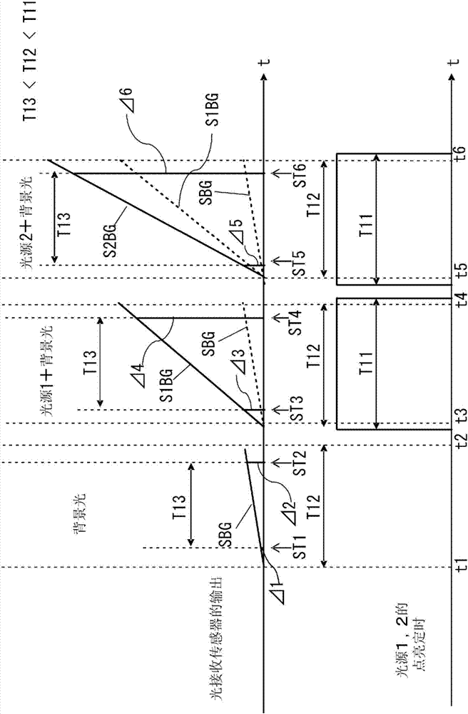
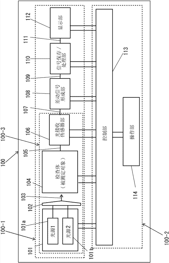
[0057] figure 1 It is a timing chart for explaining the principle of the optical gas concentration measuring method according to the present invention.

[0058] exist Figure 18 In this case, light sources 1 and 2 are turned on (ON) / off (OFF) regularly with a pulse width T11 (lighting time) as shown in the figure (the pulse width T11 is the light source light source that makes light sources 1 and 2 light up). pulse width of pulse PL).

[0059] As shown in the figure, the light-receiving sensor is regularly lit with pulse width T12 (the time when the light-receiving sensor receives light and outputs an output signal corresponding to the light-receiving amount) (the pulse width T12 is the time when the light-receiving sensor is turned on / off). pulse width of sensor drive pulse SP for OFF drive).

[0060] exist Figure 18 In the present invention, the on / off timing of the sensor driving pulse SP is within the pulse width T11 of the light source lighting pulse PL, but the pre...


PUM


Abstract

To provide a concentration measurement method with which the concentrations of predetermined chemical components can be measured non-destructively, accurately, and rapidly by a simple means, up to the concentrations in trace amount ranges, as well as a concentration measurement method with which the concentrations of chemical components in a measurement target can be accurately and rapidly measured in real time up to the concentrations in nano-order trace amount ranges, and which is endowed with a versatility that can be realized in a variety of embodiments and modes. In the present invention, a measurement target is irradiated, in a time sharing manner, with light of a first wavelength and light of a second wavelength that have different optical absorption rates with respect to the measurement target. The light of each wavelength, arriving optically via the measurement target as a result of irradiation with the light of each wavelength, is received at a shared light-receiving sensor. A differential signal is formed, the differential signal being of a signal pertaining to the light of the first wavelength and a signal pertaining to the light of the second wavelength, the signals outputted from the light-receiving sensor upon receipt of the light. The concentration of a chemical component in the measurement target is derived on the basis of the differential signal.

Description

technical field [0001] The present invention relates to an optical gas concentration measurement method related to the concentration of a predetermined chemical component in gas, and a gas concentration monitoring method based on the method. Background technique [0002] In the semiconductor manufacturing process, the mixed gas is often supplied from the same line into the processing chamber of the semiconductor manufacturing apparatus. When supplying the mixed gas, it is necessary to keep the mixing ratio of the component gases constant or to change it purposefully and instantaneously during the treatment process. Therefore, a flow control device such as a flow control system unit (FCSC) provided with a gas flow measurement mechanism and a gas flow adjustment mechanism is arranged in the gas supply line. In this FCSC, it is important to be able to accurately measure the flow rate per unit time of each component gas constituting the mixed gas (hereinafter sometimes referred...

Claims


Application Information

Patent Timeline
Patent Type & Authority Applications(China)
IPC IPC(8): G01N21/27C23C16/52G01N21/33H01L21/205
CPCC23C16/52G01N21/314G01N21/3151G01N2021/3155G01N2021/3159G01N2021/3181G01N2201/0696G01N33/0027G01N2201/0627G01N2201/12G01N21/27G01N21/33C23C16/18
Inventor 永瀬正明西野功二池田信一山路道雄须川成利黑田理人
Owner FUJIKIN INC
Why Eureka
Try Eureka