Welding seam tracking sensor capable of controlling electric arcs through electric and magnetic fields
A sensor and arc technology, applied in arc welding equipment, welding equipment, welding accessories, etc., can solve problems such as impact, achieve the effects of avoiding collisions, reducing residual stress, and improving welding quality
- Summary
- Abstract
- Description
- Claims
- Application Information
AI Technical Summary
Problems solved by technology
Method used
Image
Examples
Embodiment 1
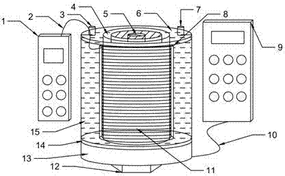
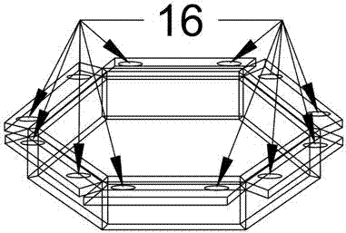
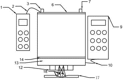
[0018] Example 1, see figure 1 and figure 2 , the sensor is mainly composed of an electric field excitation power supply, a magnetic field excitation power supply, three pairs of pole plates that generate an electric field, and a magnetic induction coil that generates a magnetic field. The sensor is fixed on the welding torch by the threaded hole of the welding torch gas cover. The outer wall of the welding torch gas cover is wrapped with a layer of heat-resistant insulation layer. The magnetic induction coil is tightly wound on the insulation of the welding torch gas cover from bottom to top. On the heat insulation layer, after winding, a layer of insulating layer is wrapped on the outer wall of the magnetic induction coil. A water storage tank is formed between the insulating layer and the outer wall of the welding torch gas cover to cool the magnetic induction coil. There is a cover plate on the upper end of the water storage tank. There are two symmetrical water inlets a...
Embodiment 2
[0032] Example 2, see image 3 , Figure 4 , Figure 5 , Figure 6 , Figure 7 , Figure 8 , is a schematic diagram of the relationship between the seam tracking sensor and the welding workpiece position of the electric and magnetic field dual-controlled arc and the corresponding Hall current waveform. The position and shape of the arc when the arc is rotated to the right, and the arc on the right is the position and shape of the arc when the arc rotates and swings to the far right. image 3 is a schematic diagram of the alignment of the sensor and the weld, Figure 4 is corresponding image 3 Hall current signal waveform diagram; Figure 5 is a schematic diagram of the position of the sensor when it is deflected to the left relative to the weld, Figure 6 is corresponding Figure 5 Hall current waveform diagram; Figure 7 is a schematic diagram of the position of the sensor when it is offset to the right of the weld seam, Figure 8 is corresponding Figure 7 Hall ...
PUM
 Abstract
Description
Claims
Application Information
 - R&D
- Intellectual Property
- Life Sciences
- Materials
- Tech Scout
- Unparalleled Data Quality
- Higher Quality Content
- 60% Fewer Hallucinations
Browse by: Latest US Patents, China's latest patents, Technical Efficacy Thesaurus, Application Domain, Technology Topic, Popular Technical Reports.
© 2025 PatSnap. All rights reserved.Legal|Privacy policy|Modern Slavery Act Transparency Statement|Sitemap|About US| Contact US: help@patsnap.com


