Strap-shaped welding wire filling-in type stirring friction treatment method

A technology of friction stir and treatment method, which is applied in welding equipment, non-electric welding equipment, metal processing equipment, etc., can solve the problems of low welding efficiency and high welding cost, and achieve the effect of improving welding efficiency, reducing welding cost and cleaning the working environment

Inactive Publication Date: 2013-06-26
HARBIN INST OF TECH
View PDF7 Cites 6 Cited by
  • Summary
  • Abstract
  • Description
  • Claims
  • Application Information

AI Technical Summary

Problems solved by technology

[0006] The purpose of the present invention is to solve the problem that most of the high-energy beam powder surfacing welding needs to be carried out smoothly under the condition of gas protection or even vacuum, the welding efficiency is low, and the welding cost is high, and a strip-shaped welding wire filling type friction stir processing method is proposed

Method used


Image

  • Strap-shaped welding wire filling-in type stirring friction treatment method
  • Strap-shaped welding wire filling-in type stirring friction treatment method
  • Strap-shaped welding wire filling-in type stirring friction treatment method

Examples


specific Embodiment approach 1

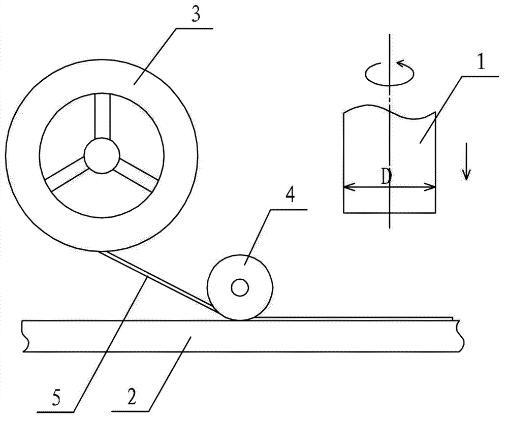
[0013] Specific implementation mode one: combine Figure 1 ~ Figure 3 Describe this implementation mode, this implementation mode is realized through the following steps:

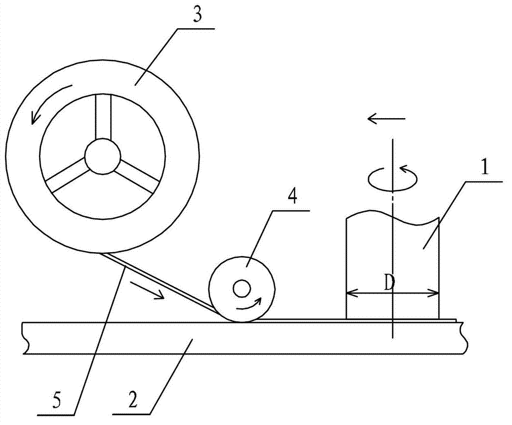
[0014] Step 1. Preparation before processing: Install and fix the wire feed roller 3 and the positioning guide wheel 4 on the main shaft of the welding machine, clamp the material 2 to be processed, place the strip welding wire 5 under the positioning guide wheel 4, and position the guide wheel 4. Wheel 4 is close to the surface of material 2 to be processed, and the strip welding wire 5 is fixed on the surface of material 2 to be processed, see figure 1 , place the end of the strip-shaped welding wire 5 directly below the needle-free welding tool 1, so that the end can be completely covered by the shoulder at the beginning of welding, and the width d of the strip-shaped welding wire 5 should be equal to or less than that of the needle-free welding The shaft shoulder diameter D of the tool 1 makes the edge...

specific Embodiment approach 2

[0017] Specific implementation mode two: combination image 3 Describe this embodiment, this embodiment is that the stirring head 1, the positioning guide wheel 4, the strip welding wire 5, and the wire feeding wheel 3 are located on the same straight line. Other steps are the same as in the first embodiment.

specific Embodiment approach 3

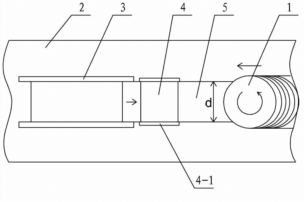
[0018] Specific embodiment three: combine 2 and image 3 Describe this embodiment. In this embodiment, flanges 4-1 are designed on both sides of the positioning guide wheel 4 in step 1, and the height of the flanges 4-1 should be greater than or equal to the thickness of the strip welding wire 5. The flange 4-1 can prevent the strip welding wire 5 from moving laterally, and the flange 4-1 guides the strip welding wire 5 to lay along the welding direction. Other steps are the same as those in Embodiment 1 or 2.


PUM


Abstract

The invention relates to a strap-shaped welding wire filling-in type stirring friction treatment method, relates to a filling-in type stirring friction treatment method, and aims at solving the problem that generally high-energy beam powder bead welding can only be conducted under gas protection or even under vacuum condition. The method comprises the following steps of: firstly, pretreatment preparation, namely, a wire feeding wheel and a positioning guide wheel are fixed on a main shaft of a welding machine, a material to be treated is clamped, a strap-shaped welding wire is put under the positioning guide wheel, the positioning guide wheel is tightly adhered to the surface of the material to be treated, the strap-shaped welding wire is fixed on the surface of the material to be treated, and the end part of the strap-shaped welding wire is put just below a needleless welding tool; secondly, stirring friction treatment, namely, the welding machine is started, the needleless welding tool starts to vertically feed downwards, the shaft shoulder of the needleless welding tool is contacted with the end part of the strap-shaped welding wire and is gradually compressed into the upper surface of the material to be treated, and the strap-shaped welding wire is subjected to bead welding on the surface of the material to be treated by using the stirring and fogging and pressing functions of the shaft shoulder; and thirdly, after-welding settlement, namely, the welding wire is cut off by using a pair of cutting nippers, the residual welding material and overlap are removed by using a steel wire brush. The method is applied to stirring friction treatment.

Description

technical field [0001] The invention relates to a filling type friction stir treatment method, in particular to a strip welding wire filling type friction stir treatment method. Background technique [0002] Friction stir processing (friction stir processing abbreviated as FSP) is a material modification and preparation technology proposed by R S M ISHRA of the University of Missouri (University of Missouri) in 2000 based on the friction stir welding (friction stir welding abbreviated as FSW) process. Friction stir welding can be used directly on the complete material without welds, and the material is directly subjected to friction stir treatment. The purpose is not welding, but a treatment to improve the properties of the metal material, such as surface treatment or melting of the metal base material. After welding, the aluminum alloy weld seam is subjected to post-weld treatment. The unique and significant advantage of FSP is that it uses frictional heat as a heat source...

Claims


Application Information

Patent Timeline
Patent Type & Authority Applications(China)
IPC IPC(8): B23K20/12
Inventor 黄永宪韩冰吕世雄万龙刘会杰冯吉才
Owner HARBIN INST OF TECH
Why Eureka
Try Eureka