
Mobile lifting device of disk bale plucker

A technology of disc catching machine and lifting device, which is applied in the direction of bale opening machine, etc., which can solve the problems of affecting cotton grabbing efficiency, cotton material cannot be sucked, and poor adjustment flexibility, etc., so as to improve grabbing efficiency and grabbing Quality, increased range and flexibility, responsive effects

Inactive Publication Date: 2017-08-04
湖州南浔凯普纺织有限公司
View PDF0 Cites 2 Cited by
  • Summary
  • Abstract
  • Description
  • Claims
  • Application Information

AI Technical Summary

Problems solved by technology

The existing cotton grabbing machine mainly consists of a cotton collecting hopper, a cotton delivery pipe, a beater and a lifting device. The existing lifting device can only perform simple up and down operations, so that the beater can only move the cotton raw material in a fixed position. Cutting; and the length of the existing beater structure is less than the gap between the ring structure silo, when the silo is filled with cotton, it will cause some of the cotton material on the edge to be unable to be sucked
Therefore, the existing technology has the problems of poor adjustment flexibility, low lifting adjustment accuracy and affecting the cotton grabbing efficiency.

Method used


Image

  • Mobile lifting device of disk bale plucker
  • Mobile lifting device of disk bale plucker
  • Mobile lifting device of disk bale plucker

Examples


Embodiment Construction

[0015] The present invention will be further described below in conjunction with the accompanying drawings and embodiments, but not as a basis for limiting the present invention.

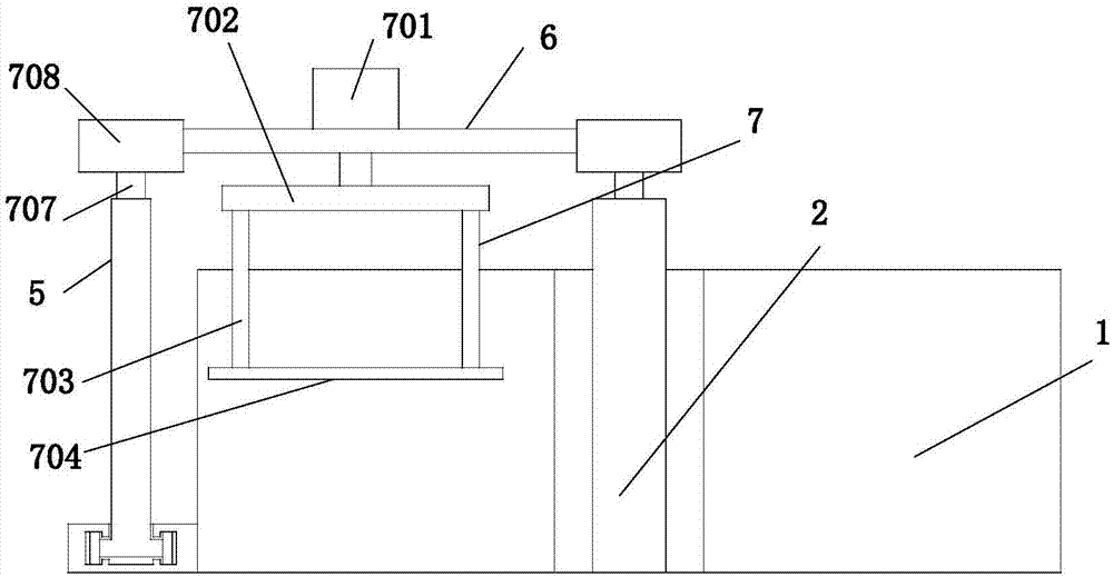
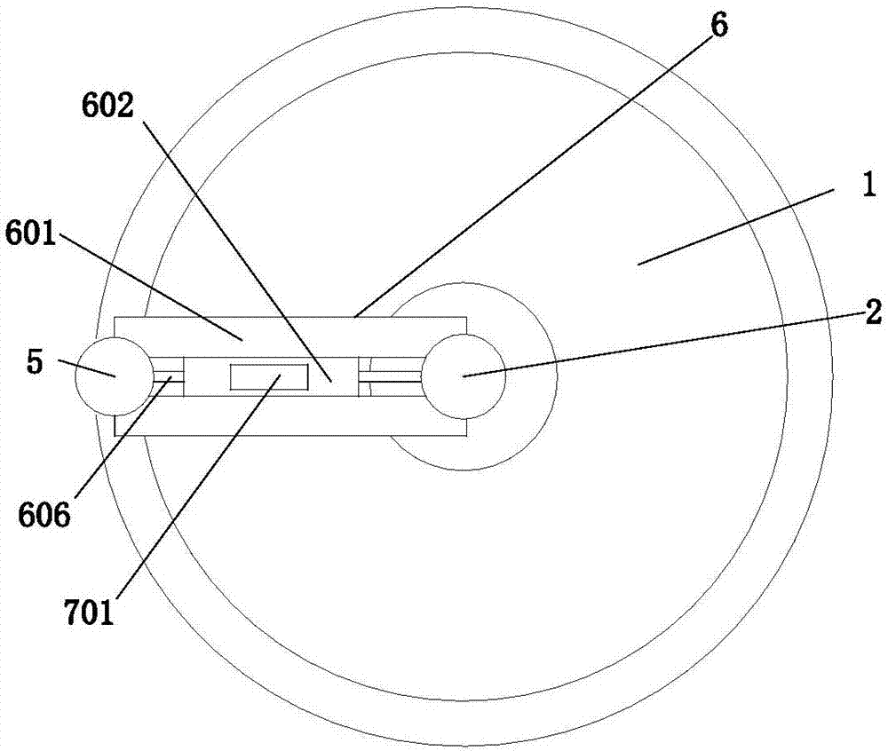
[0016] Example. A mobile lifting device of a disc plucking machine, constituted as Figure 1 to Figure 4 As shown, it includes a rotating column 2 and a driving column 5 arranged on the inner and outer sides of the annular silo 1. A supporting sliding device 6 is provided between the rotating column 2 and the driving column 5, and a lifting device is provided on the supporting sliding device 6. 7. The supporting sliding device 6 includes two supporting plates 601 arranged between the driving column 5 and the rotating column 2, a sliding plate 602 is arranged between the two supporting plates 601, and the two supporting plates 601 are opposite to each other. A T-shaped chute 603 is provided on the side wall of the T-shaped chute 603, and a pulley 604 is arranged in the T-shaped chute 603. T-shaped c...


PUM


Abstract

The invention discloses a moving lifting device of a disc bale machine, comprising a supporting sliding device (6) arranged between a rotating column (2) and a driving column (5), and the supporting sliding device (6) is provided with a lifting device device (7); the support sliding device (6) comprises two support plates (601), a sliding plate (602) is provided between the support plates (601), and a support plate (601) is provided on the opposite side wall T-shaped chute (603), the T-shaped chute (603) is provided with pulleys (604), and the two side walls of the sliding plate (602) are provided with T-shaped clamping plates corresponding to the T-shaped chute (603) (605), the two ends of the sliding plate (602) are also provided with hydraulic telescopic rods (606), and two hydraulic telescopic rods (606) are respectively fixed on the rotating column (2) and the driving column (5). The invention has the characteristics of improving the flexibility of adjustment and the precision of lifting adjustment, and also has the characteristics of improving the cotton grasping efficiency and quality.

Description

technical field [0001] The invention relates to a disc plucking machine, in particular to a moving lifting device of the disc plucking machine. Background technique [0002] Cotton yarn used in the textile industry is made from cotton fibers processed through the spinning process. In this process, it is first necessary to use the plucking machine to grab cotton bundles and cotton blocks from the bundled cotton raw materials, and then transport them to the following machinery through negative pressure pipelines for processing and production in the next step. The existing cotton grabbing machine mainly consists of a cotton collecting hopper, a cotton delivery pipe, a beater and a lifting device. The existing lifting device can only perform simple up and down operations, so that the beater can only move the cotton raw material in a fixed position. Carry out slitting; and the length of existing beater structure is less than the gap of ring structure silo, after filling cotton i...

Claims


Application Information

Patent Timeline
Patent Type & Authority Applications(China)
IPC IPC(8): D01G7/06
CPCD01G7/06
Inventor 沈新荣周云芬
Owner 湖州南浔凯普纺织有限公司
Learn More