Porphyra drying device

A drying device and technology for laver, applied in drying, drying machine, drying gas arrangement and other directions, can solve the problems of low production efficiency, large demand for manpower, low reliability, etc. The effect of improving utilization

Active Publication Date: 2017-08-08
SOUTHEAST UNIV
View PDF6 Cites 4 Cited by
  • Summary
  • Abstract
  • Description
  • Claims
  • Application Information

AI Technical Summary

Problems solved by technology

However, the centrifuge dehydration equipment needs to be filled manually, which has low reliability, large manpower demand, and low production efficiency.
The drying machine require

Method used


Image

  • Porphyra drying device
  • Porphyra drying device
  • Porphyra drying device

Examples


Embodiment Construction

[0016] The present invention will be further described below in conjunction with the accompanying drawings. Apparently, the described embodiments are only some of the embodiments of the present invention, not all of them. Based on the embodiments of the present invention, all the embodiments obtained by persons of ordinary skill in the art without making creative efforts belong to the protection scope of the present invention.

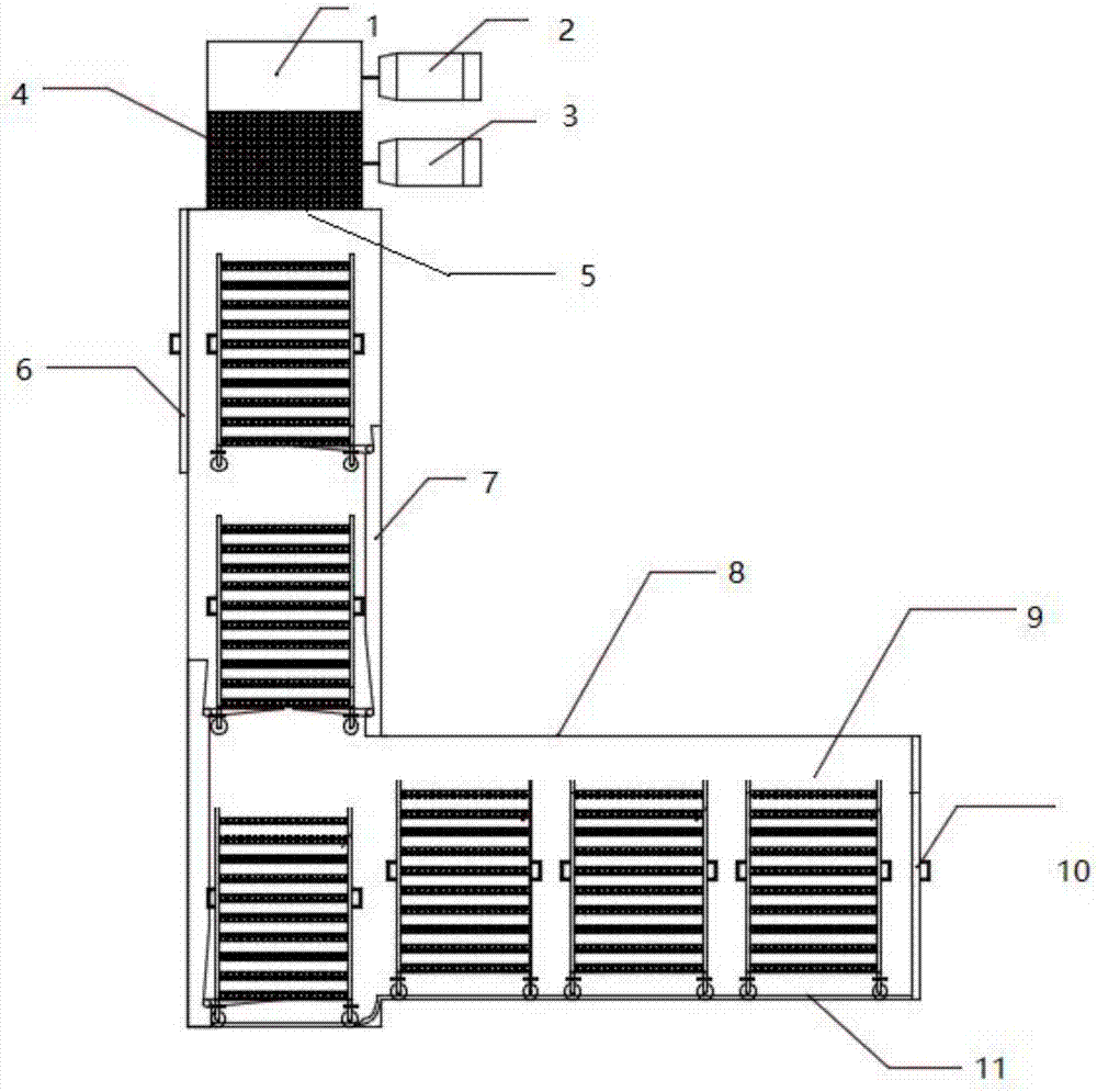
[0017] figure 1 A schematic diagram of the planar structure of the dryer is given. In this embodiment, a blower motor 2 is provided on the right side of the blower device 1, and the air outlet of the blower device 2 is located at the bottom of the device, facing the heat source device 4. A heat source motor 3 is provided on the right side of the heat source device, and the bottom of the heat source device is an outlet. The air outlet and the air outlet are connected with the uppermost air inlet of the drying pipeline 8 . The drying pipeline 8 is L-s...


PUM


Abstract

The invention discloses a porphyra drying device comprising a heat source device, an air blowing device and a drying pipeline; the heat source device is provided with an air inlet end and an air outlet end; the air blowing device is connected to the air inlet end of the heat source device; the drying pipeline is connected to the air outlet end of the heat source device and is composed of a feeding hole, a discharging hole and a charging trolley located in the pipeline; the drying pipeline is L-shaped and comprises a vertical pipeline and a horizontal pipeline in which an orbit is arranged; and longitudinal lead screw sliding tables are mounted at different heights at two sides inside the vertical pipeline. By utilizing the characteristic of large charging amount of a multilayer meshy storage rack of the charging trolley, the porphyra drying device disclosed by the invention has the effects of increasing the discharging volume within unit time and the efficiency of a dryer; and the L-shaped pipeline structure is beneficial for the dryer to sufficiently utilize hot air and is capable of prolonging the contact time with the hot air and increasing the production efficiency. Compared with a pure horizontal straight-pipeline dryer, the porphyra drying device has the advantages that the horizontal length of a space occupied by a machine is greatly reduced, and the utilization ratio of a space in a height direction is increased.

Description

technical field [0001] The invention designs a drying device, specifically a laver drying device with high energy efficiency and an L-shaped pipeline structure for drying wet laver. Background technique [0002] There is relatively little research and development on laver equipment at home and abroad, and my country's laver processing technology is still in a relatively backward position. Since 2006, China has invented the first laver processing equipment with independent intellectual property rights, but the laver drying equipment has been researched in China. Fewer and still lagging behind. It is impossible to catch up with Japan and South Korea in this field. There are three main methods of Chinese traditional laver processing: one is to use continuous pressure to dehydrate laver, the other is to use powerful centrifugal force of centrifuge to dehydrate laver, and the other is to use high-temperature dry air drying to dehydrate laver. For these three dehydration methods,...

Claims


Application Information

Patent Timeline
IPC IPC(8): F26B15/16F26B21/00
CPCF26B15/16F26B21/001F26B21/004F26B2200/16
Inventor 江志杰
Owner SOUTHEAST UNIV
Why Eureka
Try Eureka