
Liquid crystal box lens panel and liquid crystal display device

A lens panel and liquid crystal cell technology, applied in optics, instruments, nonlinear optics, etc., can solve problems such as excessive consumption, larger contact area between liquid crystal and sealant, and increased puncture risk, so as to reduce the amount of coating and save Sealant material, the effect of reducing the risk of puncture

Inactive Publication Date: 2017-08-08
SHENZHEN CHINA STAR OPTOELECTRONICS SEMICON DISPLAY TECH CO LTD
View PDF5 Cites 4 Cited by
  • Summary
  • Abstract
  • Description
  • Claims
  • Application Information

AI Technical Summary

Problems solved by technology

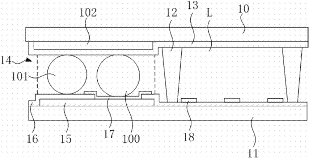
[0004] Ordinary LCD cells are about 3.5 μm thick, and the liquid crystal cell lens panel requires at least 20 μm of liquid crystal cell thickness to ensure the lens effect. The thickness of the sealing area 14 of the liquid crystal cell lens panel is conventionally designed to match the display area of ​​the liquid crystal cell lens panel. The gap L is similar, so the liquid crystal lens will have the following disadvantages when it is produced on an ordinary LCD production line: (1) It consumes nearly 5 times more sealant materials; The diameter of the fiber ball 101 and the metal ball 100; (3) The contact area between the liquid crystal and the sealant becomes larger, and the risk of puncture increases

Method used


Image

  • Liquid crystal box lens panel and liquid crystal display device
  • Liquid crystal box lens panel and liquid crystal display device
  • Liquid crystal box lens panel and liquid crystal display device

Examples


Embodiment Construction

[0020] The specific implementation manners of the liquid crystal cell lens panel and the liquid crystal display device provided by the present invention will be described in detail below in conjunction with the accompanying drawings.

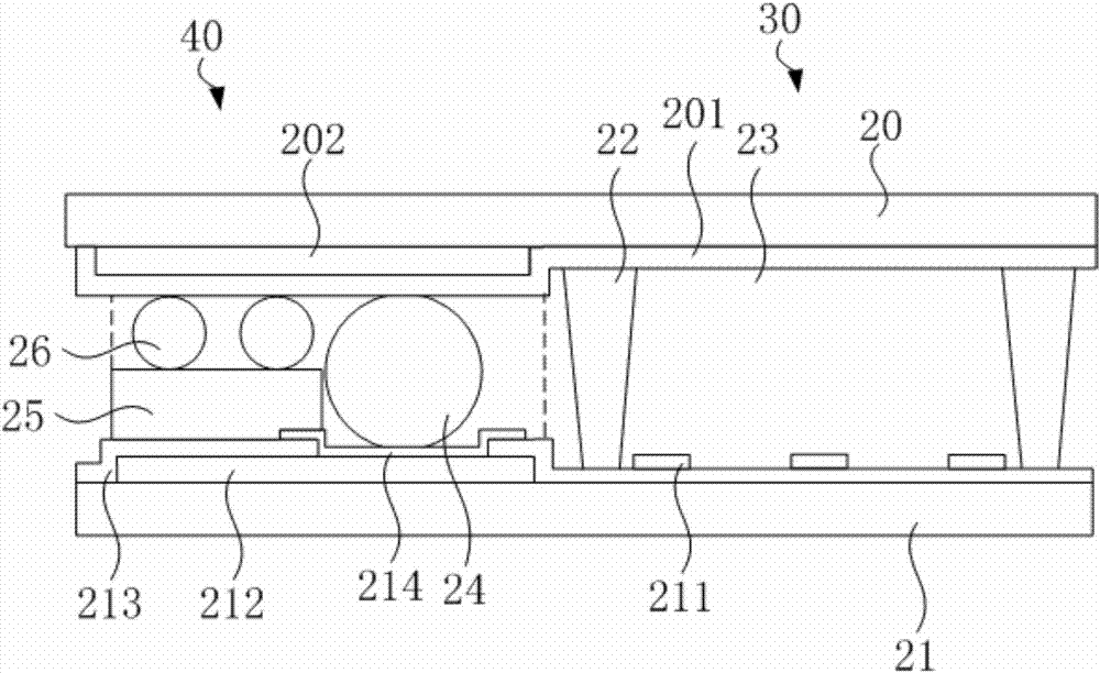
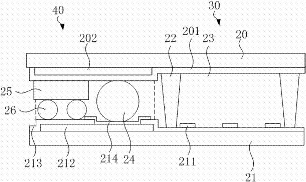
[0021] see figure 2 , In the first embodiment of the liquid crystal cell lens panel of the present invention, the liquid crystal cell lens panel includes a first substrate 20 and a second substrate 21 , and the second substrate 21 is disposed opposite to the first substrate 20 . The liquid crystal cell lens panel includes a display area 30 and a sealing area 40 located around the display area, and the display area 30 corresponds to the display area of ​​the liquid crystal display device.

[0022] An upper electrode 201 is disposed on the surface of the first substrate 20 , and the upper electrode 201 is a whole electrode extending from the display area 30 to the sealing area 40 . In the display area 30 , a lower electrode 211 is provided on th...


PUM


Abstract

The invention provides a liquid crystal box lens panel and a liquid crystal display device. The liquid crystal box lens panel comprises a first substrate, and an upper electrode is arranged on the surface of the first substrate; a second substrate is arranged relative to the first substrate; a first photo spacer is arranged between the first substrate and the second substrate to form a gap; edges of the first substrate and the second substrate are sealed to form a sealed area; the surface of the second substrate is provided with a metal trace in the sealed area, the surface of the metal trace is provided with a passivation layer with a via hole, and a transparent electrode penetrates through the via hole to be electrically connected with the metal trace; and a second photo spacer is arranged on the surface of the passivation layer and / or the surface of the upper electrode to reduce the width of a gap of the sealed area, and the gap of the sealed area is filled with a sealant. The invention has the following advantages: when a liquid crystal display panel production line is adopted to manufacture the liquid crystal box lens panel, the diameters of fiber balls are not increased; a sealant material is saved, and the discharge capability of a sealant spray nozzle of equipment is not increased; and the contact area between a liquid crystal and the sealant is reduced, and a puncture risk is reduced.

Description

technical field [0001] The invention relates to the field of liquid crystal display, in particular to a lens panel of a liquid crystal cell and a liquid crystal display device. Background technique [0002] In the current mainstream naked-eye 3D display technology, liquid crystal lens technology has become an important development direction because it can flexibly realize the switching of 2D / 3D mode without significantly affecting the 2D mode display. The basis of liquid crystal lens technology is to simulate the light adjustment function of the microstructure lens so that pixels in different regions are projected into the left and right eyes respectively, so that images with parallax can be synthesized in the brain for a three-dimensional effect. [0003] figure 1 It is the structure of the conventional liquid crystal cell lens panel. see figure 1 As shown, a conventional liquid crystal cell lens panel includes a first substrate 10 , a second substrate 11 and a spacer 12...

Claims


Application Information

Patent Timeline
Patent Type & Authority Applications(China)
IPC IPC(8): G02F1/1343G02F1/1339G02F1/1335G02B27/22
CPCG02B30/27G02F1/133512G02F1/1339G02F1/134309
Inventor 刘林峰
Owner SHENZHEN CHINA STAR OPTOELECTRONICS SEMICON DISPLAY TECH CO LTD
Learn More