

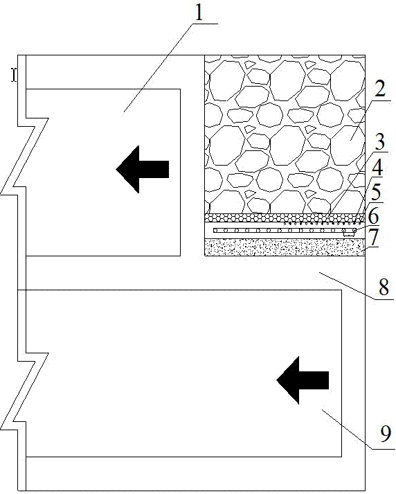
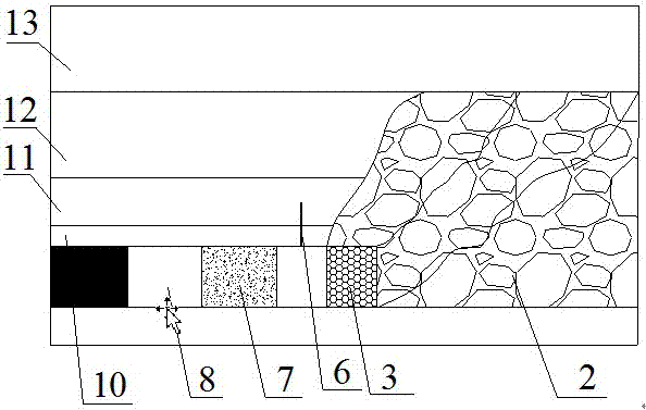
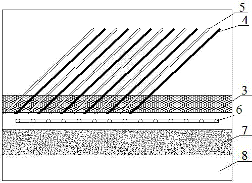
Roof cutting and pressure releasing method for double-filling wall structure in gob-side entry retaining
A technology for roof cutting, pressure relief, and wall filling. It is applied in the directions of backfill, earthwork drilling, and bolt installation. It can solve problems such as harming the staff at the end, difficult to control the reaction time of the cracking agent, and affecting the construction of backfill walls.
- Summary
- Abstract
- Description
- Claims
- Application Information
AI Technical Summary
Problems solved by technology
Method used
Image

Examples
Embodiment Construction
[0023] Specific embodiments of the present invention are further described below.
[0024] To implement the above-mentioned method of roof cutting and pressure relief for gobside entry retaining and double filling wall structure provided by the present invention is carried out according to the following steps:
[0025] Step 1. Build the first high-water material filling wall 7
[0026] (1) The high-water material is composed of two components, material A and material B, wherein material A is Portland cement, retarder and suspending agent, and its mass ratio is 9:0.2:0.8; material B is gypsum , lime, accelerator and suspending agent, the mass ratio is 7:2.4:0.2:0.4; the retarder used is a mixture of citric acid, tartaric acid and their salts; the accelerator used is bauxite, Clinker mixture made of soda ash and quicklime; the suspending agent used in material A is a mixture of bentonite, cellulose ether and starch ether; the suspending agent used in material B is a mixture of ...
PUM
| Property | Measurement | Unit |
|---|---|---|
| width | aaaaa | aaaaa |
| diameter | aaaaa | aaaaa |
Abstract
Description
Claims
Application Information