Turbine blade trailing edge turbulent flow half-wedge type seam cooling structure with array pin fins

A technology for turbine blades and cooling structures, applied in the directions of blade support elements, engine elements, machines/engines, etc., can solve problems such as tendency to limit, and achieve the effect of reducing the maximum temperature and average temperature, with reasonable design and simple structure

Inactive Publication Date: 2017-08-11
NORTHWESTERN POLYTECHNICAL UNIV
View PDF8 Cites 16 Cited by
  • Summary
  • Abstract
  • Description
  • Claims
  • Application Information

AI Technical Summary

Problems solved by technology

[0004] In the literature "Experimental Research on the Air Film Cooling Characteristics of Turbine Blade Trailing Slits" ("Journal of Engineering Thermophysics", 2016, No. 37, pp. 1988-1993), the thermochromic liquid crystal transient heat transfer measurement was used to study The effects of two different split rib structures, straight rib and chamfered rib, on the film cooling characteristics of the split ribs in the trailing edge laminate cooling structure are studied, although the conclusion shows that the air film cooling effect of the half-slit trailing edge of the blade is affected by the split ribs. However, with the continuous increase of the gas temperature of the aero-engine, the cooling capacity of the traditional half-slit structure gradually tends to the limit, and the ablation phenomenon of the trailing edge of the high-pressure turbine blade often occurs on the suction side of the trailing edge of the blade, so the development of And the innovative efficient cooling structure of the trailing edge of the turbine blades can further improve the comprehensive cooling effect without increasing the amount of cooling air, which is very necessary and meaningful for the development of advanced high-performance aero-engines

Method used


Image

  • Turbine blade trailing edge turbulent flow half-wedge type seam cooling structure with array pin fins
  • Turbine blade trailing edge turbulent flow half-wedge type seam cooling structure with array pin fins
  • Turbine blade trailing edge turbulent flow half-wedge type seam cooling structure with array pin fins

Examples


Embodiment Construction

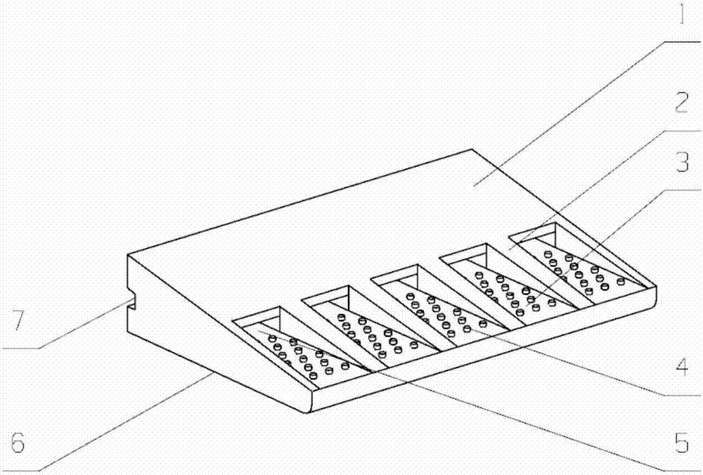
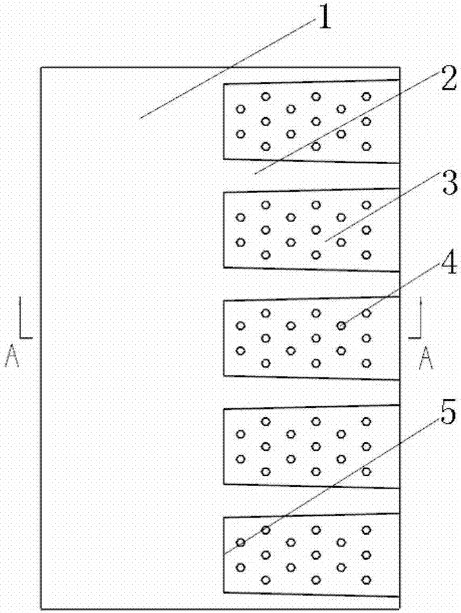
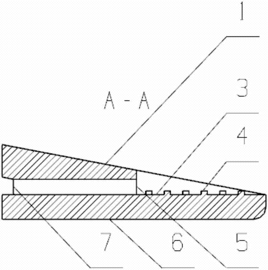
[0023] This embodiment is a turbine blade trailing edge turbulent half-slit cooling structure with array pin fins.

[0024] refer to Figure 1 to Figure 6 In this embodiment, the turbine blade trailing edge turbulent half-slit cooling structure with array pin ribs is applied to an aeroengine turbine blade, and the turbulent half-slit cooling structure is applied to the trailing edge region 8 of the turbine blade. edge suction surface 6, blade trailing edge pressure surface 1, trailing edge half-split wall surface 3, partition rib 2, array pin rib 4, cold flow outlet 5, and cold flow inlet 7; Part of the wall surface, the wall surface on the side that retains the suction surface 6 of the blade trailing edge and the spaced partition ribs 2 form a plurality of half-slit structures; the ratio of the thickness t of the lip plate of the half-slit structure to the height s of the cold air outlet slot is 0.2 to 1.5 , the inclination angle of the half-slit is 0-15°, and the cooling ai...


PUM


Abstract

The invention discloses a turbine blade trailing edge turbulence half-slit cooling structure with an array of pin ribs. The array of pin ribs is applied to the half-slit wall surface, and the flow turbulence structure is passed without increasing the outflow of the gas film. Improve the convective heat transfer coefficient and heat transfer area of ​​the air film, and enhance the convective heat transfer intensity of the half-slit air film cooling, thereby improving the comprehensive cooling effect of the trailing edge of the blade. Turbine blade trailing edge turbulent half-split cooling structure with continuous array of needle ribs cuts off part of the wall on the pressure surface of the blade trailing edge, retains the wall on the suction side of the blade trailing edge and separates the partition ribs to form multiple half-splits Slit structure, the cooling air flow is ejected from the cold flow outlet and covers the split wall of the trailing edge to form a cooling air film. The structure is simple; the maximum temperature and average temperature of the suction surface can be effectively reduced, and high-temperature ablation of the suction surface of the turbine blade can be avoided. The straight rib structure is arranged on the half-slit wall surface, which has good heat transfer characteristics and good processing feasibility.

Description

technical field [0001] The invention belongs to the technical field of turbine blade cooling of a gas turbine, and in particular relates to a turbine blade trailing edge turbulence half-slit cooling structure with array pin fins. Background technique [0002] Increasing the turbine inlet temperature is an effective way to improve the thrust and efficiency of gas turbines, but the increase in turbine inlet temperature will cause the turbine blades to bear a greater heat load, and excessive temperature and thermal stress may cause the turbine blades to fail to work properly. The inlet temperature of modern gas turbine design has far exceeded the temperature limit of the materials used, so complex cooling technology must be used to ensure the normal operation of the turbine under high temperature conditions. The trailing edge of the turbine blade is often a high-temperature part, and it is also most likely to be damaged by thermal corrosion. The design of its cooling structure ...

Claims


Application Information

Patent Timeline
Patent Type & Authority Applications(China)
IPC IPC(8): F01D5/18
CPCF01D5/186F05D2240/304
Inventor 刘存良谢刚叶林魏建生朱惠人
Owner NORTHWESTERN POLYTECHNICAL UNIV
Why Eureka
Try Eureka