Eureka AIR delivers breakthrough ideas for toughest innovation challenges, trusted by R&D personnel around the world.

Laser welding technology of bypass valve rod and valve sheet

A laser welding and bypass valve technology, applied in laser welding equipment, welding equipment, manufacturing tools, etc., can solve the problems of diameter expansion, deformation, softening, etc.

Inactive Publication Date: 2017-08-11
ZHEJIANG YINLUN MACHINERY
View PDF4 Cites 3 Cited by
  • Summary
  • Abstract
  • Description
  • Claims
  • Application Information

AI Technical Summary

Problems solved by technology

[0003] The purpose of the present invention is to provide a manufacturing process for the bypass valve in the exhaust gas recirculation of engine exhaust, which is used to solve the problem of softening the valve stem and the valve plate due to the brazing connection process between the valve stem and the valve plate of the traditional bypass valve. Deformation, and prevent the valve stem from bending when the eccentric wheel and the valve stem are subsequently riveted, prevent the diameter of the valve stem from expanding at the joint between the valve stem and the sealing bushing, and effectively control the material cost of the bypass valve product

Method used


Image

  • Laser welding technology of bypass valve rod and valve sheet
  • Laser welding technology of bypass valve rod and valve sheet
  • Laser welding technology of bypass valve rod and valve sheet

Examples


Embodiment Construction

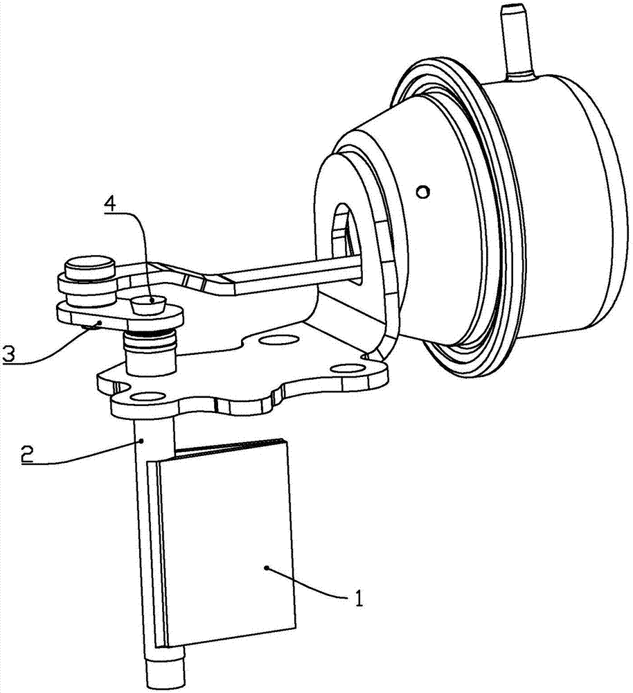
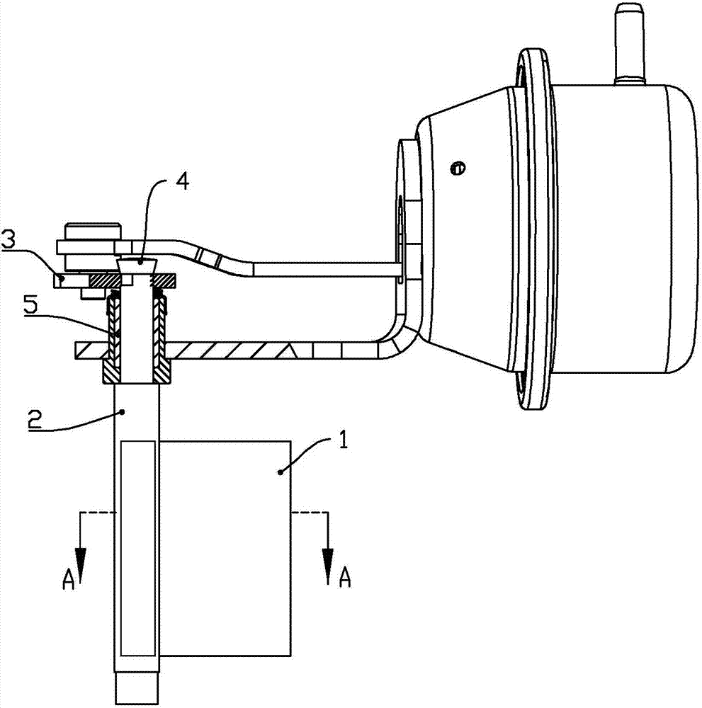
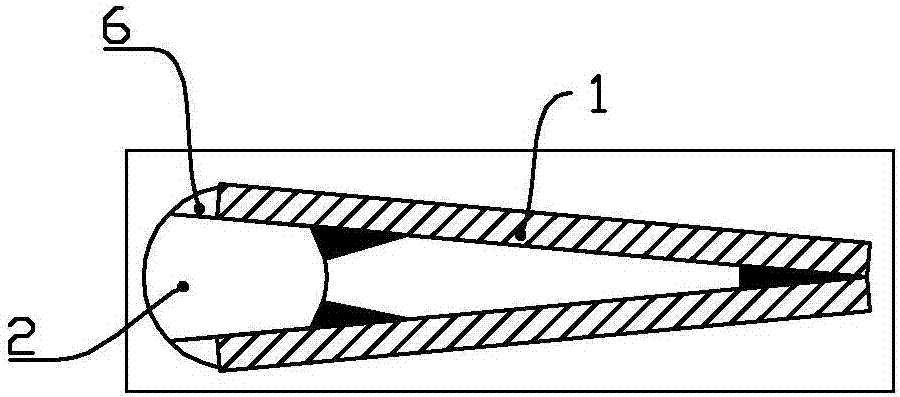
[0016] Below in conjunction with accompanying drawing, the present invention will be further described with specific embodiment, see Figure 1-4 :

[0017] A manufacturing process for a bypass valve in exhaust gas recirculation of engine exhaust gas, comprising a valve stem 2 and a valve plate 1, the valve stem 2 and valve plate 1 are assembled and connected by laser welding.

[0018] Further, the valve plates 1 are a pair and fixed at an angle, and the heads of the valve plates 1 are fixed by laser welding; the valve stem 2 is symmetrically provided with a chamfered surface 6, and the inner surface of the tail of the valve plate 1 is parallel to fit on the chamfered face 6 and fixed by laser welding.

[0019] Further, after the valve stem 2 is connected with the valve plate 1, the head of the valve stem 2 is connected with the eccentric wheel 3 by screw riveting.

[0020] Further, the laser welding is carried out at normal temperature.

[0021] Further, the bonding force b...


PUM


Abstract

A manufacturing technology of a bypass valve in engine exhaust gas exhausting and recycling involves a valve rod and a valve sheet which are assembled and then are connected through a laser welding technological mode. With the adoption of the manufacturing technology of the bypass valve in engine exhaust gas exhausting and recycling, the problem of softening and deforming of the valve rod and the valve sheet in a traditional soldering connecting technology of the bypass valve rod and the valve sheet can be solved; the valve rod can be prevented from being bent while screwing and riveting an eccentric wheel and the valve rod in later period; the diameter of the valve rod at the part where the valve rod is in match with a sealing shaft sleeve is prevented from increasing; and the material cost of the bypass valve product can be effectively controlled.

Description

technical field [0001] The invention belongs to the technical field of engine exhaust emission control devices, in particular to a manufacturing process of a bypass valve in exhaust gas recirculation of engine exhaust emission. Background technique [0002] The bypass valve plays the role of opening and closing the recirculation exhaust gas in the exhaust gas recirculation system of the automobile engine. The opening and closing of the valve port in the bypass valve requires a valve stem and a valve plate. The valve stem and the valve plate are different parts before assembly, and they need to be welded to form a whole. During the normal working process of the bypass valve, the eccentric wheel drives the valve stem to rotate in the sealing sleeve, so that the valve plate closes the exhaust gas flow to different valve ports. The connection strength between the plates needs to be above 18KN. At present, the connection between the valve plate and the valve stem generally adopt...

Claims


Application Information

Patent Timeline
Patent Type & Authority Applications(China)
IPC IPC(8): F02M26/71B23K26/21
CPCB23K26/21
Inventor 丁天满潘凯邓树平洪宗川
Owner ZHEJIANG YINLUN MACHINERY
Why Eureka
Eureka Blog
Learn More