Energy saving nozzle of minimum quantity lubrication system

A technology of minimal quantity lubrication and nozzles, which is applied in the direction of injection devices, injection devices, liquid injection devices, etc.

Active Publication Date: 2017-08-15
SHANGHAI JINZHAO ENERGY SAVING TECH +1
View PDF4 Cites 7 Cited by
  • Summary
  • Abstract
  • Description
  • Claims
  • Application Information

AI Technical Summary

Problems solved by technology

[0007] In view of the above problems, in order to solve the deficiencies in the application of existing three-phase flow micro-lubrication nozzles, the purpose of the present invention is to provide an energy-saving nozzle for a micro-quantity lubrication system

Method used


Image

  • Energy saving nozzle of minimum quantity lubrication system
  • Energy saving nozzle of minimum quantity lubrication system
  • Energy saving nozzle of minimum quantity lubrication system

Examples


Embodiment 1

[0123] Example as figure 1 As shown in Figure 6, Embodiment 2 is improved on the basis of Embodiment 1, as Figure 7 to Figure 1 1.

[0124] Embodiment 1 will be further described below in conjunction with the accompanying drawings.

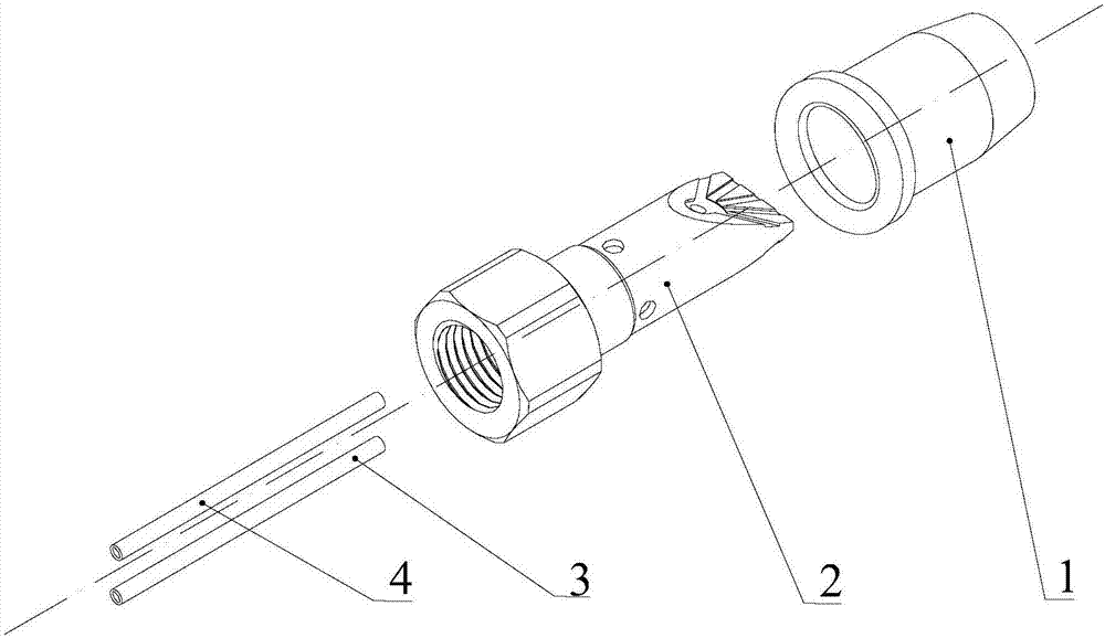
[0125] figure 1 It is a three-dimensional assembly diagram of an energy-saving nozzle for a minimal quantity lubrication system.

[0126] Such as figure 1 As shown, an energy-saving nozzle of a minimal quantity lubrication system includes: a nesting ring 1 , a nozzle body 2 , a lubricating oil input conduit 3 and a water input conduit 4 .

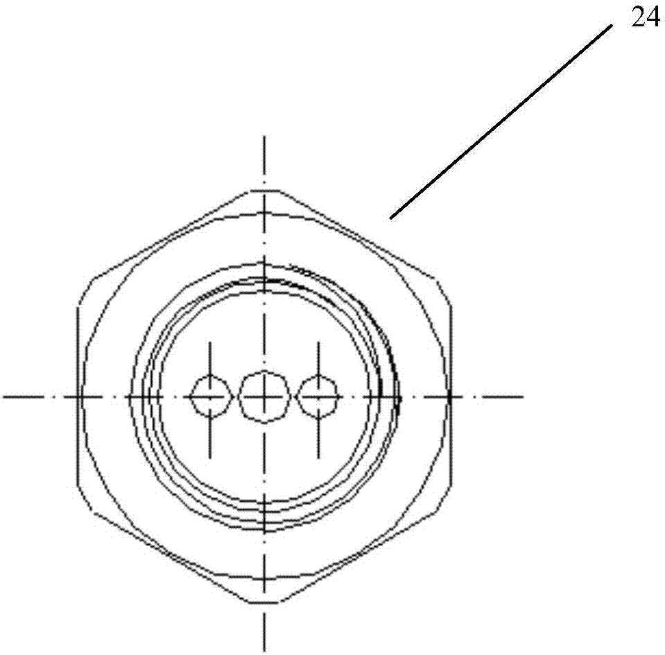
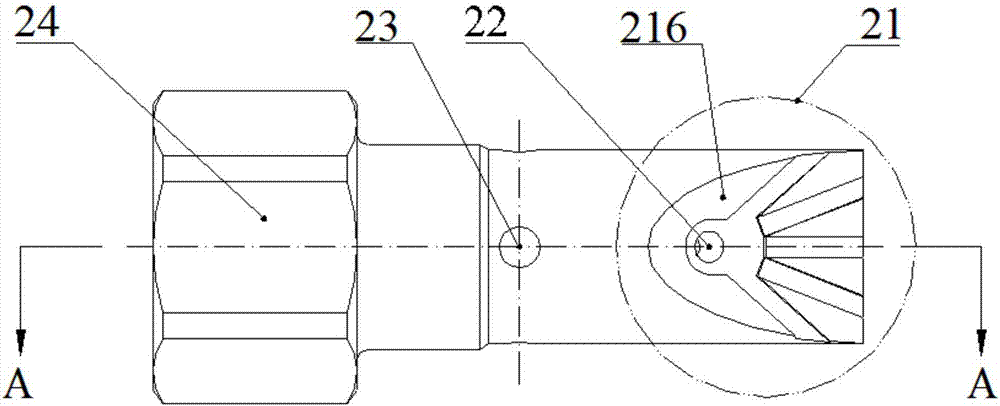
[0127] Fig. 2 is a three-view view of the nozzle body.

[0128] image 3 It is a sectional view of an energy-saving nozzle of a minimal quantity lubrication system.

[0129] Combining Figure 2 and image 3 Description of nozzle body 2:

[0130] The nozzle body 2 includes: diversion groove unit 21, water output hole 22, gas output hole 23, connection fixing unit 24, lubricating oil output hole 25, wate...

Embodiment 2

[0167] Embodiment 2 Compared with Embodiment 1, the lubricating oil and water are mixed instantaneously when they are sprayed out of the nozzle, instead of being mixed inside the nozzle. The change of structure makes the mixing of lubricating oil and water more fully, and achieves better spray effect.

[0168] To sum up, the present invention is applied to the supply of micro-quantity lubricating oil and water, which realizes the uniform lubrication of the line contact processing form, solves the application bottleneck of the existing nozzle point lubrication, improves the efficiency of the three-phase flow oil, water and air supply, and effectively reduces the The problem of pollution to the working environment provides a new way for the high-efficiency, low-carbon, and energy-saving applications of minimal quantity lubrication.


PUM


Abstract

The invention provides an energy saving nozzle of a minimum quantity lubrication system. The energy saving nozzle of the minimum quantity lubrication system is characterized by comprising an embedding ring and a nozzle body; the embedding ring is embedded on the outer side of the nozzle body, totally or partially covers the surface of the nozzle body, and is in clearance fit with the nozzle body; an air cavity and at least two fluid channels are formed in the nozzle body; an air hole and a hole for penetrating through the internal of the nozzle body are formed in the surface of the nozzle body; a guide groove unit is arranged on the surface of the nozzle body; and with a liquid hole as a starting point, the guide groove unit is multiple symmetric guide groove bodies scattered on the surface of the nozzle body. The nozzle structure generates fan-shaped spray to spray to a cutting area, so that the supply problem of minimum quantity lubrication cutting liquid with a machining mode as linear contact is preferably solved, the liquid supply to the cutting area is uniform, and the cooling lubrication performance of minimum quantity lubrication is improved.

Description

technical field [0001] The invention belongs to the technical field of mechanical technology, and relates to an energy-saving nozzle of a micro-quantity lubrication system and the system thereof. Background technique [0002] Traditional machining uses a large amount of emulsion, cutting oil, coolant, etc. to cool and lubricate the processing area. This cooling and lubricating method has low utilization rate and increases the huge processing and production costs. Moreover, if the waste coolant is not handled properly, it will cause serious damage to the environment. big damage. Dry processing technology is the earliest green and environmental protection processing technology, which originated in the automobile industry. It has been successfully used in machining such as turning, milling, drilling and boring. It is not simply to completely abandon cutting fluid, but to abolish the use of cutting fluid on the premise of ensuring the machining accuracy of parts and the servic...

Claims


Application Information

Patent Timeline
Patent Type & Authority Applications(China)
IPC IPC(8): B05B1/04B05B7/00B23Q11/10
CPCB05B1/04B05B7/00B23Q11/10
Inventor 张彦彬吴启东张乃庆李长河邱秋敏
Owner SHANGHAI JINZHAO ENERGY SAVING TECH
Why Eureka
Try Eureka