
Photodynamic therapy system with tissue image and light spot boundary visualization function

A photodynamic therapy, tissue image technology, applied in the directions of therapy, phototherapy, radiotherapy, etc., can solve the problem of inability to visually see the tissue image and the position of the light spot of the therapeutic fiber in the cavity, reduce the accuracy and safety of the treatment, and cannot. Real-time judgment of lesion response and other issues, to avoid blind operation, avoid over-irradiation, and improve the effect of treatment

Inactive Publication Date: 2017-08-18
GENERAL HOSPITAL OF PLA
View PDF12 Cites 7 Cited by
  • Summary
  • Abstract
  • Description
  • Claims
  • Application Information

AI Technical Summary

Problems solved by technology

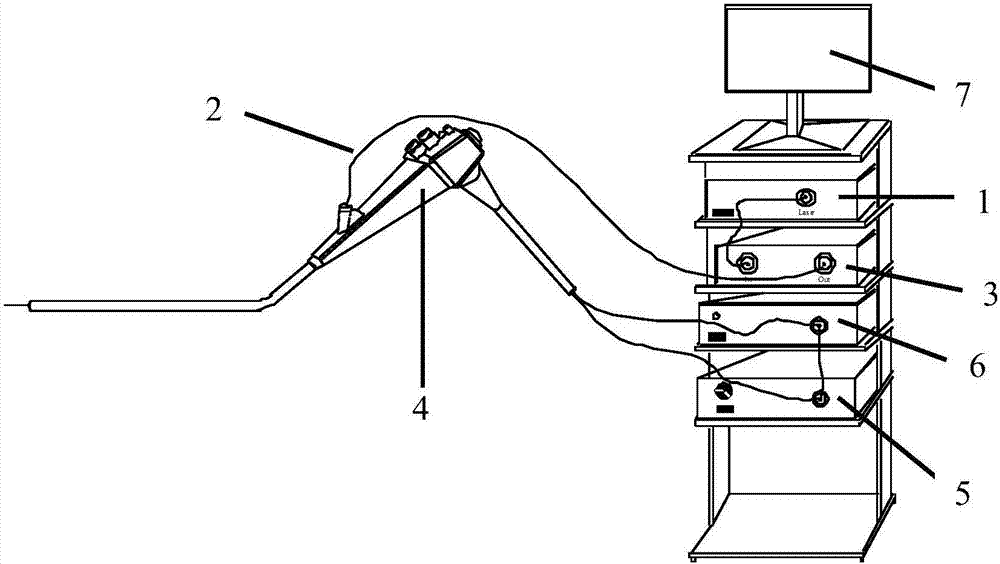
[0004] The technical problem to be solved by the present invention is to provide a photodynamic therapy system with the function of visualizing tissue images and spot boundaries, aiming to solve the problem that the display screen is bright white due to the high output power of the photodynamic therapy light source, which causes doctors to During the whole treatment process, it is impossible to visually see the tissue image and the position of the light spot of the treatment fiber in the cavity, and it is impossible to judge the response of the lesion in real time, which greatly reduces the accuracy and safety of treatment and increases the risk of surgery.

Method used

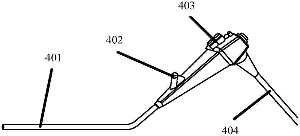
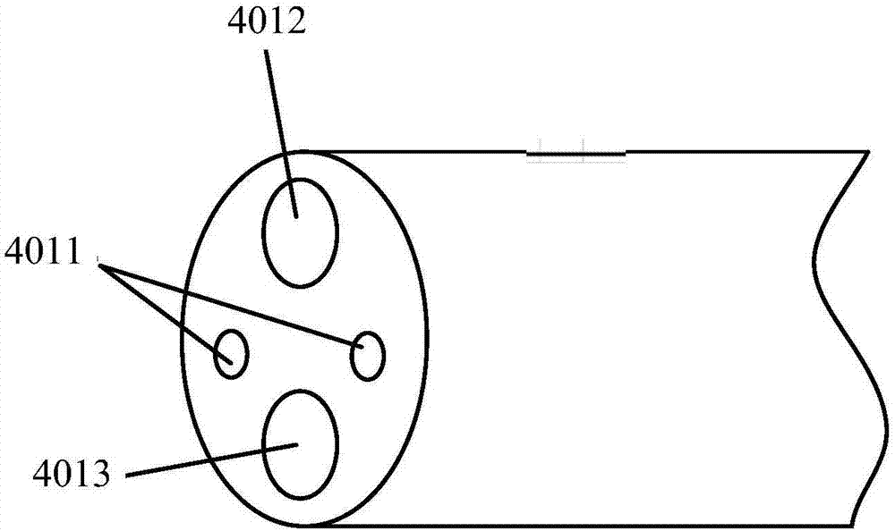

Image

  • Photodynamic therapy system with tissue image and light spot boundary visualization function
  • Photodynamic therapy system with tissue image and light spot boundary visualization function
  • Photodynamic therapy system with tissue image and light spot boundary visualization function

Examples


Embodiment Construction

[0030] In order to make the objectives, technical solutions and advantages of the present invention clearer, the following further describes the present invention in detail with reference to the accompanying drawings and embodiments. It should be understood that the specific embodiments described herein are only used to explain the present invention, but not to limit the present invention.

[0031] The main realization idea of ​​the present invention is to provide a photodynamic therapy system with visible function of tissue image and spot boundary. The system introduces spectral cut-off technology and light multiplexing technology into the photodynamic therapy system, and uses spectral cut-off technology to prevent electrons. The CCD or CMOS optical system receives the reflected or scattered treatment laser, and at the same time receives the imaging light from the front end of the electronic endoscope to realize the visualization of the tissue image; and the optical coupler in th...


PUM

PropertyMeasurementUnit
Lengthaaaaaaaaaa
Diameteraaaaaaaaaa

Abstract

The invention is applicable to the technical field of photodynamic therapy, and provides a photodynamic therapy system with a tissue image and light spot boundary visualization function. On the one hand, an electronic CCD (Charge-coupled Device) or CMOS optical system in an electronic endoscope blocks reflected or scattered therapeutic laser while receiving illumination light, thereby being capable of realizing tissue image visualization; and on the other hand, the therapeutic laser and indication light are coupled through a coupler and outputted to a diseased tissue of the human body together by an output optical fiber via the electronic endoscope, and the indication light and the therapeutic laser are the same in light emitting region, so that the position of a therapeutic light spot can be determined through an indication light spot formed by reflected or scattered indication light, thus the boundary of the therapeutic light spot is displayed in real time through recognizing the boundary of the indication light spot, and a tissue image with the boundary of the therapeutic light spot is provided for a doctor. The photodynamic therapy system provided by the invention realizes authentic and visual images in the photodynamic therapy process and enables the doctor to accurately see a positional relation between the therapeutic light spot and the diseased tissue.

Description

Technical field [0001] The invention belongs to the technical field of photodynamic therapy, and in particular relates to a photodynamic therapy system with visual functions of tissue image and spot boundary. Background technique [0002] Regarding cancer, in the current treatment methods, if surgery is used, the patient's body will be traumatized due to the need for thoracic surgery; if radiotherapy and chemotherapy are adopted, the systemic side effects of radiation and chemotherapy will be strong, which will reduce the body’s normal immunity. Function, poor quality of life after treatment, and long-term survival rate is not yet ideal. Facing the current status of the treatment of malignant tumors, there is an urgent need to develop new targeted therapies with less trauma and side effects. [0003] Photodynamic therapy (PDT) is a new technology that is in line with the development direction (targeted, localized, and individualized) of tumor treatment in the 21st century. It has ...

Claims


Application Information

Patent Timeline
IPC IPC(8): A61N5/06A61N5/067A61B1/04A61B1/07A61B1/012A61B1/00
CPCA61B1/00009A61B1/00064A61B1/00131A61B1/012A61B1/042A61B1/07A61N5/062A61N2005/0626A61N2005/0632A61N2005/0664A61N5/067
Inventor 邵永红顾瑛
Owner GENERAL HOSPITAL OF PLA
Learn More