
Corrugated plate for wet processes desulphurization tower and airflow distributing device thereof

An air distribution device and wet desulfurization technology, applied in gas treatment, separation method, dispersed particle separation, etc., can solve the problem of reducing desulfurization efficiency, absorption tower synergistic dust removal efficiency, affecting gas-liquid two-phase mass transfer effect, and uneven distribution of flue gas. and other problems, to achieve the effect of improving the synergistic dust removal effect, convenient installation and disassembly and maintenance, and simple structure

Inactive Publication Date: 2017-08-18
武汉立为工程技术有限公司
View PDF4 Cites 5 Cited by
  • Summary
  • Abstract
  • Description
  • Claims
  • Application Information

AI Technical Summary

Problems solved by technology

However, after the flue gas enters the absorption tower body, the volume will expand rapidly and the speed will slow down. Affected by the absorption tower wall, a part of the flue gas flows upward along the opposite side of the absorption tower entrance, while the other part of the flue gas moves downward and flows at the bottom of the absorption tower. A counterclockwise vortex is formed near the pool, resulting in a strong turbulent flow area, resulting in extremely uneven distribution of flue gas in the tower, affecting the mass transfer effect between the gas-liquid two phases, reducing the desulfurization efficiency and the synergistic dust removal efficiency of the absorption tower

Method used


Image

  • Corrugated plate for wet processes desulphurization tower and airflow distributing device thereof
  • Corrugated plate for wet processes desulphurization tower and airflow distributing device thereof

Examples


Embodiment Construction

[0019] In order to make the objectives, technical solutions and advantages of the present invention clearer, the present invention will be further described in detail below with reference to the accompanying drawings and embodiments. It should be understood that the specific embodiments described herein are only used to explain the present invention, but not to limit the present invention.

[0020] As a preferred embodiment of the present invention:

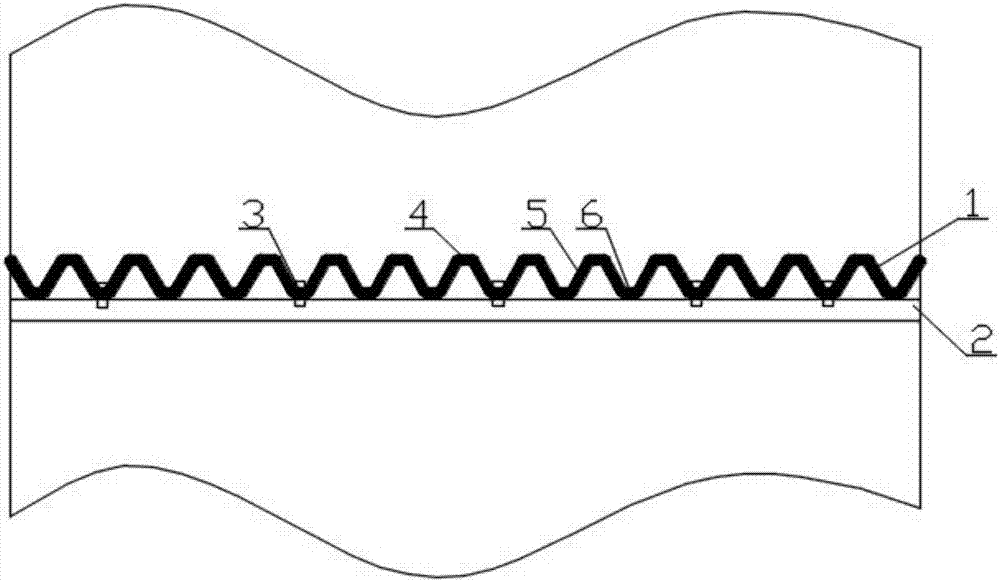
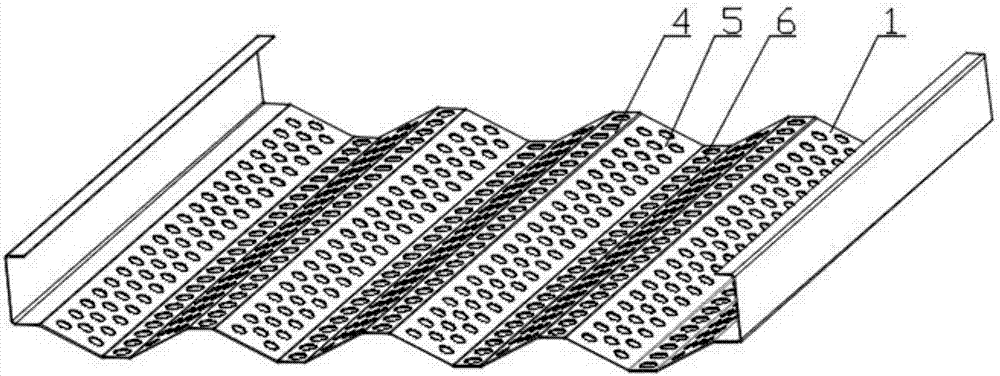
[0021] see figure 1 and figure 2 , a corrugated plate for a wet desulfurization tower, comprising a corrugated plate module, the corrugated plate module consists of a plurality of parallel valley plates 6 and peak plates 4 and connecting the valley plates 6 and the peak plates 4 with an inclined angle The side wall plate 5 is integrally formed, the ratio of the width of the peak plate 4 and the valley plate 6 to the width of the side wall plate 5 is 1 / 3 to 2 / 3, and the vertical distance between the peak plate 4 and the valley ...


PUM


Abstract

The invention relates to a corrugated plate for wet processes desulphurization tower and an airflow distributing device composed of the corrugated plate. The corrugated plate comprises a plurality of horizontally arranged corrugated plate modules and supporting beams, wherein each corrugated plate module is integrally formed by a plurality of mutually parallel valley and peak plates and side wall plates connected with the valley and peak plates and having inclination angles, a plurality of round through holes are uniformly distributed in the valley plates, the side wall plates and the peak plates, and the corrugated plate modules are connected and fixed to the supporting beams through bolts. The corrugated plate can achieve effective flue gas rectification, airflows are mutually interfered through optimal parameter values due to inclined arrangement of the side wall plates after flue gas passes through the airflow distributing device, and the flue gas flowing speed is reduced, so that the flue gas in a tower is uniform in distribution, falling slurry drops form a liquid film on the surface of the corrugated plate, the standing time of the slurry is prolonged, mass transfer between two phases of air and liquid is enhanced, the desulphurization efficiency is improved, and a synergic flue gas dust removal effect is improved. By arranging the bolts and the supporting beams, the corrugated plate is simple in structure and convenient to install, dismount and maintain.

Description

technical field [0001] The invention relates to the field of auxiliary equipment of a flue gas desulfurization device, in particular to a corrugated plate used in a wet desulfurization tower and an air distribution device thereof. Background technique [0002] The flue gas emitted by coal-fired power plants contains a large amount of sulfur dioxide. If it is directly discharged without treatment, it will cause great harm to the environment and economic development. With the increasingly stringent environmental protection standards, power companies have stepped up efforts to control sulfur dioxide. The limestone-gypsum wet flue gas desulfurization technology is currently the most widely used and mature desulfurization process, and the absorption tower is the core equipment of the process. The boiler flue gas enters the tower from the inlet flue of the absorption tower, the flue gas rises, and in the absorption area, it contacts with the gypsum slurry sprayed down from the up...

Claims


Application Information

Patent Timeline
Patent Type & Authority Applications(China)
IPC IPC(8): B01D53/81B01D53/50
CPCB01D53/502B01D53/504B01D53/81B01D2258/0283
Inventor 梅晟东孙园园熊巍
Owner 武汉立为工程技术有限公司
Learn More