
Biological-chemical combined conditioning equipment and method

A technology of chemical combination and chemical conditioning, applied in chemical instruments and methods, biological sludge treatment, sludge treatment, etc., can solve the corrosion of structures and equipment pipelines caused by conditioning sludge, the reduction of organic matter content in dewatered sludge, and the value of recycling Zero and other problems, to achieve the effect of improving oxidation effect, saving dosage, and enhancing adaptability

Active Publication Date: 2017-08-18
JIANGSU KAIMI MEMBRANE TECH
View PDF6 Cites 2 Cited by
  • Summary
  • Abstract
  • Description
  • Claims
  • Application Information

AI Technical Summary

Problems solved by technology

[0003] Sludge has the characteristics of high water content, high organic matter content, and high germ content. If it is piled up randomly without proper treatment, it will cause huge damage to the environment.
At present, the commonly used sludge deep dehydration conditioning technology is to add FeCl to the remaining sludge 3 and CaO, the dosage is usually 3% to 5% and 15% to 20% of the weight of the dry matter of the sludge. The addition of too much inorganic matter will increase the volume of the sludge by about 20%, and the organic matter content of the dewatered sludge will be significantly reduced. The calorific value of sludge is reduced, and the recycling value is almost zero
[0004] Bioleaching conditioning technology needs to reduce the sludge to a lower pH to achieve deep dehydration conditioning of the sludge. Although this technology has a good sludge conditioning effect, it is unstable under low temperature conditions, and the conditioning sludge has a negative impact on structures and structures. Severe corrosion of equipment and pipelines

Method used


Image

  • Biological-chemical combined conditioning equipment and method
  • Biological-chemical combined conditioning equipment and method

Examples


Embodiment Construction

[0031] The present invention is described in further detail now in conjunction with accompanying drawing.

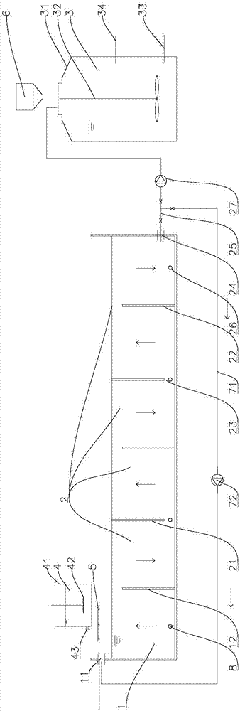
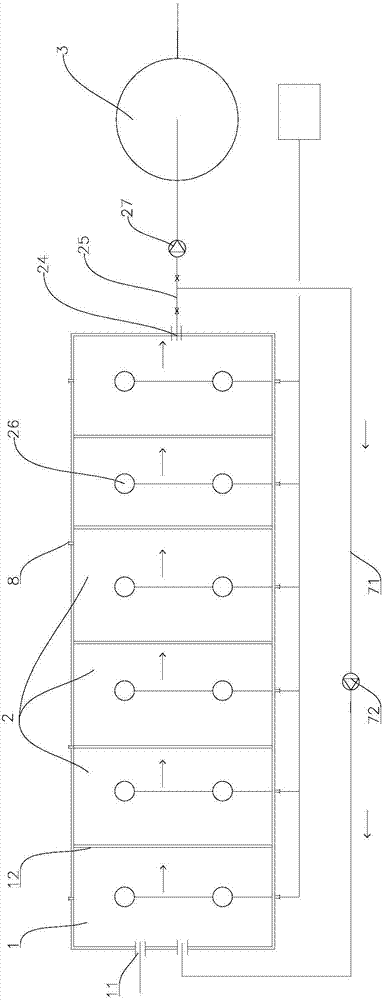
[0032] A biological-chemical combined conditioning equipment, including sequentially arranged: a biological selection tank 1, a bioleach reaction tank 2 and a chemical conditioning tank 3, the biological selection tank 1 is provided with a mud inlet 11, the biological selection tank 1 and the bioleach A partition 12 with a height lower than the side wall of the bioselective tank 1 and the side wall of the bioleaching reaction tank 2 is provided between the reaction tanks 2. The bioleaching reaction tank 2 is a square box structure with several alternately arranged upper walls. The baffle plate 21 and the lower baffle plate 22, the upper baffle plate 21 is fixedly connected with the side wall of the bioleaching reaction tank 2, and forms a gap 23 for the passage of sludge with the bottom plate of the bioleaching reaction tank 2, and the lower baffle plate 22 It is fixedly...


PUM

PropertyMeasurementUnit
heightaaaaaaaaaa

Abstract

The invention relates to the technical field of deep dewatering treatment of sludge, in particular to efficient biological sludge conditioning equipment. The efficient biological sludge conditioning equipment comprises a biological selection pond, a biological leaching reaction pond and a chemical conditioning tank which are arranged in sequence. The biological selection pond is provided with a sludge inlet, a low partition plate is arranged between the biological selection pond and the biological leaching reaction pond, a plurality of upper baffles and lower baffles are alternately arranged in the biological leaching reaction pond, and the biological leaching reaction pond is communicated with the chemical conditioning tank through a sludge outlet pipe; aerators are arranged in the biological selection pond and the biological leaching reaction pond. For the defects in the prior art, a biological-chemical combined conditioning system and method of excess sludge are provided; biological leaching conditioning is conducted on sludge by inoculation of a composite biological leaching strain, strong corrosion of biologically leached sludge is avoided, and the sludge conditioning effect is further ensured; with the assistance of a chemical conditioning agent, the dewatering rate is further increased, and meanwhile the influence of the chemical conditioning agent on the heat value of dewatered sludge is reduced.

Description

technical field [0001] The invention relates to the technical field of sludge deep dehydration treatment, in particular to a set of biological high-efficiency sludge conditioning equipment and a method thereof. Background technique [0002] Municipal sludge is a by-product of sewage treatment with a large amount of pollutants produced during the treatment of urban domestic sewage and industrial wastewater by sewage plants. For a long time, my country's sewage industry generally has a tendency to "heavy water and light mud". With the rapid increase of my country's sewage treatment rate, the sludge output has also increased. In 2016, the municipal sludge has reached more than 30 million tons (calculated with a moisture content of 80%). [0003] Sludge has the characteristics of high water content, high organic matter content, and high germ content. If it is piled up randomly without proper treatment, it will cause huge damage to the environment. At present, the commonly used...

Claims


Application Information

Patent Timeline
Patent Type & Authority Applications(China)
IPC IPC(8): C02F11/02C02F11/14
CPCC02F11/02C02F11/14C02F2303/06Y02W10/20
Inventor 刘杰马昊彭娜王怀林曹敏周龙坤
Owner JIANGSU KAIMI MEMBRANE TECH
Learn More