
Device for carbonizing biomass by electromagnetic wave

A biomass and electromagnetic wave technology, applied in the field of machinery, can solve the problems of electromagnetic wave recovery, unable to intelligently control the feeding speed, low feeding efficiency, etc., to achieve the effect of improving efficiency, efficient and intelligent control of feeding speed, and improving carbonization efficiency.

Inactive Publication Date: 2017-08-18
JIAXING VOCATIONAL TECHN COLLEGE
View PDF6 Cites 3 Cited by
  • Summary
  • Abstract
  • Description
  • Claims
  • Application Information

AI Technical Summary

Problems solved by technology

[0004] Although the above-mentioned electromagnetic wave biomass pyrolysis continuous reaction device can continuously carbonize biomass, the device cannot recover the excess heat generated by electromagnetic waves, nor can it intelligently control the feeding speed, resulting in low feeding efficiency

Method used


Image

  • Device for carbonizing biomass by electromagnetic wave
  • Device for carbonizing biomass by electromagnetic wave
  • Device for carbonizing biomass by electromagnetic wave

Examples


Embodiment 1

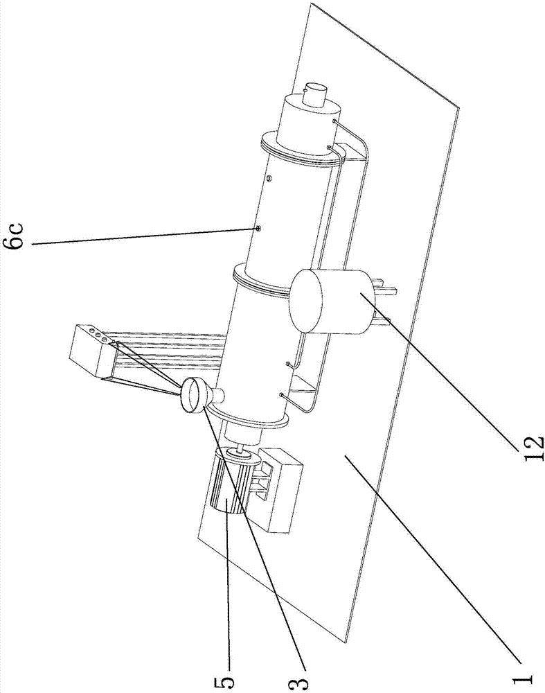
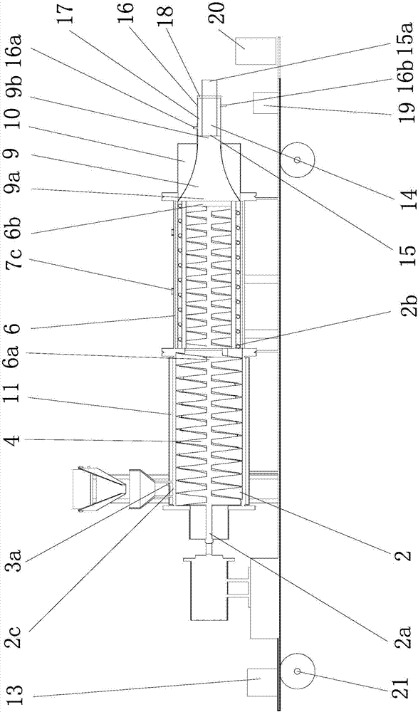
[0031] Such as figure 1 , figure 2 with Image 6 As shown, the equipment for biomass carbonization using electromagnetic waves includes a frame 1, on which a feeding device is arranged, and the feeding device includes a feeding cylinder 2 with a channel 1 inside, and the axial direction of the feeding cylinder 2 Perpendicular to the direction of gravity, the feeding cylinder 2 is fixed on the frame 1, one end of the feeding cylinder 2 has an outlet 2b, the other end of the feeding cylinder 2 is provided with an installation opening 2a, and the upper part of the feeding cylinder 2 is provided with a feeding opening 2c , the feeding port 2c communicates with the inner channel of the feeding cylinder 2, the feeding hopper 3 is arranged at the feeding port 2c, the feeding port 2c is close to the end of the installation port 2a, and the feeding tube 2 is provided with a The screw feeder 4 that the installation port 2a transports towards the direction of the outlet 2b, the end of...

Embodiment 2

[0044] The content in the second embodiment is roughly the same as that in the first embodiment, except that the cooling device in the second embodiment includes a cooling pipe one and a cooling pipe two sleeved outside the cooling pipe, the cooling pipe one and the cooling pipe There is a cavity between the two tubes, the end of the cooling tube one and the end of the cooling tube two are kept sealed by the annular sealing plate, one end of the cooling tube one has a feed port one, and the other end of the cooling tube one has a discharge port 1. The feed inlet 1 is connected with the outlet of the above-mentioned discharge cylinder, and the cooling pipe 1 is kept sealed with the discharge cylinder. A water inlet hole is opened on the cooling pipe 2. The water inlet hole can provide ice through the water inlet pipe. The water ice water generator is connected; the cooling pipe 2 is also provided with a liquid recovery hole, and the liquid recovery hole is connected with the ice...


PUM

PropertyMeasurementUnit
sizeaaaaaaaaaa
sizeaaaaaaaaaa

Abstract

The invention provides a device for carbonizing biomass by electromagnetic wave, and belongs to the technical field of a machine. The device solves the technical problems that efficiency of the existing carbonizing device is low and the heat energy cannot be recycled, and others. The device for carbonizing biomass by the electromagnetic wave comprises a frame, wherein a feeding device is arranged on the frame and comprises a feeding cylinder with a first channel inside; the upper part of the feeding cylinder is provided with a feeding opening, and the feeding opening is connected with the first channel at inside of the feeding cylinder; the feeding opening is provided with a feeding hopper, and a spiral feeder is arranged in the feeding cylinder; a carbonizing cylinder is further fixed on the frame, one end of the carbonizing cylinder is provided with a carbonizing cylinder inlet while the other end is provided with a carbonizing cylinder outlet; the carbonizing cylinder and the feeding cylinder are sealed; a discharging cylinder is further fixed on the frame, the discharging cylinder and the carbonizing cylinder are sealed; a heat recycling device for recycling heat in the discharging cylinder is further arranged at outside of the discharging cylinder. The device for carbonizing biomass by the electromagnetic wave has the advantages of high carbonizing efficiency, good carbonizing quality, and the like.

Description

technical field [0001] The invention belongs to the technical field of machinery, and relates to a carbonization device, in particular to a device for carbonizing biomass by using electromagnetic waves. Background technique [0002] With the development of science and technology, the large-scale use and exploitation of conventional mineral energy such as oil, coal and natural gas, under the dual pressure of energy shortage and environmental damage, the development of energy has become an urgent consideration, and bio-energy cracking technology as One of the most potential biomass conversion technologies. As a large agricultural country, our country is rich in biomass resources, mainly agricultural waste. Under such conditions, China has listed biomass energy utilization technology as a key research and development object. [0003] In order to solve the above problems, after searching, it is found that Chinese patent literature discloses a continuous reaction device and meth...

Claims


Application Information

Patent Timeline
Patent Type & Authority Applications(China)
IPC IPC(8): C10B53/02
CPCC10B53/02Y02E50/10
Inventor 向天勇秦国栋张正红单胜道
Owner JIAXING VOCATIONAL TECHN COLLEGE
Learn More