Valve lift control device of fully variable hydraulic valve mechanism and internal combustion engine

A valve mechanism and valve lift technology, applied in valve devices, machines/engines, mechanical equipment, etc., can solve the problems of long transmission chain, difficult layout of hydraulic transmission system, etc., and achieve the effect of reducing leakage

Active Publication Date: 2017-08-18
SHANDONG UNIV
View PDF4 Cites 6 Cited by
  • Summary
  • Abstract
  • Description
  • Claims
  • Application Information

AI Technical Summary

Problems solved by technology

This mechanism is mainly suitable for the air distribution mechanism with the camshaft on the top, but for the air distribution mechanism with the camshaft below and in the middle, it is difficult to install the device under the camshaft due to the difficult layout of the hydraulic transmission system and the long transmission chain. Popularization and application on internal combustion engines

Method used


Image

  • Valve lift control device of fully variable hydraulic valve mechanism and internal combustion engine
  • Valve lift control device of fully variable hydraulic valve mechanism and internal combustion engine
  • Valve lift control device of fully variable hydraulic valve mechanism and internal combustion engine

Examples


Embodiment 1

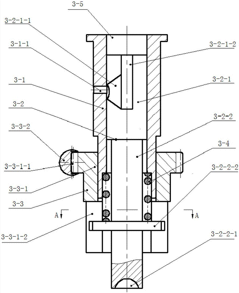
[0058] like Figure 5 As shown, the distance between the upper edge of the circumferential annular groove 3-2-1-1 and the top end of the plunger 3-2 gradually increases from the axial straight groove 3-2-1-2 along the circumferential direction of the plunger 3-2 , the depth of the circumferential annular groove 3-2-1-1 gradually decreases from the axial straight groove 3-2-1-2 along the circumferential direction of the plunger 3-2, and the circumferential annular groove 3-2-1-1 The cross section is triangular.

[0059] In this embodiment, when the required maximum valve lift becomes smaller and the valve closing time is earlier, the plunger adjustment mechanism 3-3 adjusts the rotation angle of the plunger 3-2 so that the circumferential annular groove 3-2-1-1 The part close to the axial straight groove 3-2-1-2 communicates with the oil drain hole 3-1-1, because the distance between the upper edge of this part of the circumferential annular groove 3-2-1-1 and the top of the p...

Embodiment 2

[0061] like Image 6 As shown, the cross section of the circumferential annular groove 3-2-1-1 is arc-shaped, and the rest of the structure is the same as that of Embodiment 1.

Embodiment 3

[0063] like Figure 7 As shown, the distance between the upper edge of the circumferential annular groove 3-2-1-1 and the top end of the plunger 3-2 gradually increases from the axial straight groove 3-2-1-2 along the circumferential direction of the plunger 3-2 , the distance from the lower edge to the top of the plunger 3-2 is constant from the axial straight groove 3-2-1-2 along the circumferential direction of the plunger 3-2, and the depth of the circumferential annular groove 3-2-1-1 is constant Change. When the plunger adjustment mechanism 3-3 adjusts the plunger 3-2 to rotate different angles, the timing when the circumferential annular groove 3-2-1-1 communicates with the oil drain hole 3-1-1 is different, so that the plunger oil The moment when the chamber 3-5 and the piston oil chamber 5-4 flow into the energy storage chamber 9 through the oil drain hole 3-1-1 also changes accordingly, causing the maximum lift of the valve to also change thereupon.


PUM


Abstract

The invention discloses a valve lift control device of a fully variable hydraulic valve mechanism and an internal combustion engine, and belongs to the field of air distribution mechanisms and fuel supply systems of internal combustion engines. When a plunger of the valve lift control device ascends to the position where a circumferential annular groove and an oil leakage hole communicate, hydraulic oil in a plunger oil cavity and a piston oil cavity flows into an energy storage cavity through an axial straight groove, the circumferential annular groove, the oil leakage hole and a first low-pressure oil duct, and the pressure and amount of oil in the plunger oil cavity and the piston oil cavity are reduced, so that the maximum lift of a valve is reduced, and the valve falls back in advance. By controlling the rotation angle of the plunger, changing duration of communication of the circumferential annular groove and the oil leakage hole, adjusting the minimum effective circulation area formed by the circumferential annular groove and the oil leakage hole, and controlling the amount of hydraulic oil flowing out of the oil leakage hole, the maximum lift and descending time of the air valve are changed. The valve lift control device is simple in structure, reliable in operation, low in cost and suitable for internal combustion engines with cam shafts on the upper portions, lower portions and middles.

Description

technical field [0001] The invention relates to the field of a gas distribution mechanism and a fuel supply system of an internal combustion engine, in particular to a fully variable hydraulic valve mechanism valve lift control device and an internal combustion engine. Background technique [0002] The internal combustion engine adopts a hydraulically driven valve system that can realize the continuous variable of the maximum valve lift, valve opening continuous angle and valve timing. This valve system is called a fully variable hydraulic valve system (Hydraulic Fully Variable Valve System, HFVVS for short). , which is of great significance to the energy saving and emission reduction of internal combustion engines. At present, representative fully variable hydraulic valve systems include the Uniair system of Schaeffler Company, the electro-hydraulic fully variable valve system of Ford Company in the United States, and the EHFVVT system of Lotus in the United Kingdom. These...

Claims


Application Information

Patent Timeline
Patent Type & Authority Applications(China)
IPC IPC(8): F01L13/00F01L9/02F01L9/12F01L9/14F01L9/40
CPCF01L13/0015F01L9/12
Inventor 谢宗法常英杰王志明王兆宇
Owner SHANDONG UNIV
Why Eureka
Try Eureka