
Vehicle shock absorber bushing

A shock absorber and bushing technology, which is applied to springs/shock absorbers, springs made of plastic materials, mechanical equipment, etc., can solve the problems of poor heat aging resistance, poor heat dissipation, damage and scrapping, etc. High strength, good shock absorption and good heat dissipation

Pending Publication Date: 2017-08-18
南漳富元鼎航空器材配件有限公司
View PDF9 Cites 1 Cited by
  • Summary
  • Abstract
  • Description
  • Claims
  • Application Information

AI Technical Summary

Problems solved by technology

[0003] The traditional automobile vibration reduction technology uses elastic deformation of rubber to absorb part of the vibration energy of the vibration source and transmit it to the vehicle body after vibration isolation, so as to achieve partial vibration reduction and noise reduction. In the process, the elastic deformation of rubber will quickly produce a large number of However, the heat dissipation performance of the rubber itself is poor, especially when the working environment temperature exceeds 80°C, and then subjected to a certain load force, the shock absorber bushing made of old-fashioned rubber materials has poor thermal aging resistance. It will quickly age, and it will be damaged and scrapped after 3 to 4 months of use. It must be replaced. Therefore, the rubber shock absorber bushing becomes a vulnerable and consumable part, and frequent replacement will bring more troubles. , such as increasing the cost of using the car for the car owner, frequent disassembly and assembly of auto parts will also cause hidden dangers in safety. Long life cycle, while ensuring low cost, shock absorber bushing products that can be widely used in all series of models

Method used


Image

  • Vehicle shock absorber bushing
  • Vehicle shock absorber bushing

Examples


Embodiment Construction

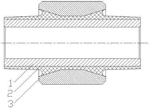
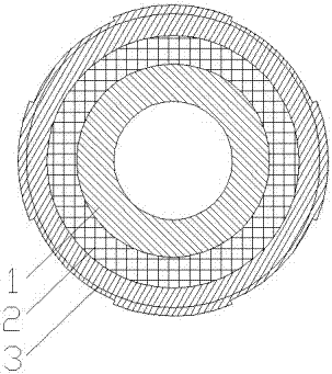
[0023] figure 1 , 2 Among them, the shock absorber bushing is installed on the main body of the shock absorber and the vehicle body through the outer tube 3, and then connected to the tire suspension and other components through the outer tube 3. The vibration of the body itself is weakened by the outer tube 3 and then transmitted to the rubber layer 2 for absorption and digestion. , and then transferred to the body structure through the inner tube 1, and the heat generated by the elastic deformation of the rubber layer 2 is dissipated into the air by the inner tube 1 and the outer tube 3. Similarly, the vibration generated by the contact between the body and the road surface is weakened in the opposite order After absorption, it is transmitted to other parts of the body to play a two-way damping function.


PUM


Abstract

The invention discloses a vehicle shock absorber bushing. The vehicle shock absorber bushing comprises an inner tube, an outer tube and a rubber sleeve layer, wherein the inner wall of the rubber sleeve layer wraps and is attached to the outer surface of the inner tube; a bump part is arranged on the middle part of the rubber sleeve layer; the outer tube is positioned outside the bump part; a concave part is arranged on the bump part; and a convex part which is in contact with the concave part is arranged on the inner wall of the outer tube. According to the vehicle shock absorber bushing disclosed by the invention, the thickness of the middle part of the outer tube made of a magnesium alloy material is increased, so that the clearance between the thickness of the middle part of the outer tube made of the magnesium alloy material and the inner tube is reduced, and therefore, shaking during travelling of a vehicle is reduced; clearance between the thickness of the end part of the outer tube made of the magnesium alloy material and the inner tube is a bit greater than the middle part, so that collision of the outer tube and the inner tube when the vehicle travels in a twisting mode is reduced; and meanwhile, bonding of the inner tube and the outer tube is facilitated, so that bonding strength is improved by 30% or more. The vehicle shock absorber bushing has the advantages of good vibration damping performance, good radiation and a long service life cycle.

Description

technical field [0001] The invention belongs to the field of automobile vibration reduction and noise reduction, in particular to an automobile shock absorber bushing. Background technique [0002] Automobile shock absorber bushings, also known as automobile suspension shock absorber bushings, and engine suspension shock absorbers, steering gear shock absorbers, shock absorbers, shock absorbers, shock absorbers and other components, They are all part of the car's shock absorption system. After the car is started, whether it is initially idling or driving at high speed, vibration will be generated due to the friction between the tire and the road surface, road bumps, etc., especially when the car engine itself is running. Vibration will form a vibration source , thus causing noise, these vibrations will reduce the service life of auto parts, and have a great impact on driving controllability, riding comfort and vehicle safety, so automotive vibration reduction technology has ...

Claims


Application Information

Patent Timeline
Patent Type & Authority Applications(China)
IPC IPC(8): F16F1/38
CPCF16F1/38
Inventor 宋彭川钱昌平王智慧
Owner 南漳富元鼎航空器材配件有限公司
Learn More