Tube nest type fluoroplastic flue gas-flue gas heat exchanger

A technology of flue gas heat exchanger and fluoroplastic, which is applied in the direction of heat exchanger shell, indirect heat exchanger, heat exchanger type, etc., can solve the problem of high cost of equipment body and engineering transformation, large area occupied by metal GGH, System operation power consumption and other issues, to achieve the effect of eliminating gypsum rain and white smoke, convenient site layout, and reducing operating costs

Inactive Publication Date: 2017-08-18
北京新世翼节能环保科技股份有限公司
View PDF6 Cites 6 Cited by
  • Summary
  • Abstract
  • Description
  • Claims
  • Application Information

AI Technical Summary

Problems solved by technology

[0010] The above-mentioned methods all have different problems. The metal GGH occupies a large area, the cost of the equipment body and engineering transformation is high, the site layout is difficult, the resistance of the equipment is above 1000Pa, and the power consumption of the system is considerable. In addition, during the operation of the equipment itself Problems such as leakage, corrosion and wear have not been well resolved, which also restricts its continuous engineering application
The zero-leakage water-medium flue gas reheating system MGGH occupies a small area, the cost of engineering transformation is low, the equipment resistance is small, and the layout is relatively simple, but the system structure is relatively complicated, and the power consumption of the pump and the consumption of other operating materials cannot be ignored
Due to the consideration of anti-corrosion, the wet electrostatic demister has a very high equipment cost. In order to ensure the demisting effect, the flue gas flow rate needs to be reduced very low, so the volume of the equipment is even larger, and it is difficult to arrange on site. Few industry applications, little practical experience

Method used


Image

  • Tube nest type fluoroplastic flue gas-flue gas heat exchanger
  • Tube nest type fluoroplastic flue gas-flue gas heat exchanger
  • Tube nest type fluoroplastic flue gas-flue gas heat exchanger

Examples


Embodiment Construction

[0060] The present invention is further described below in conjunction with embodiment.

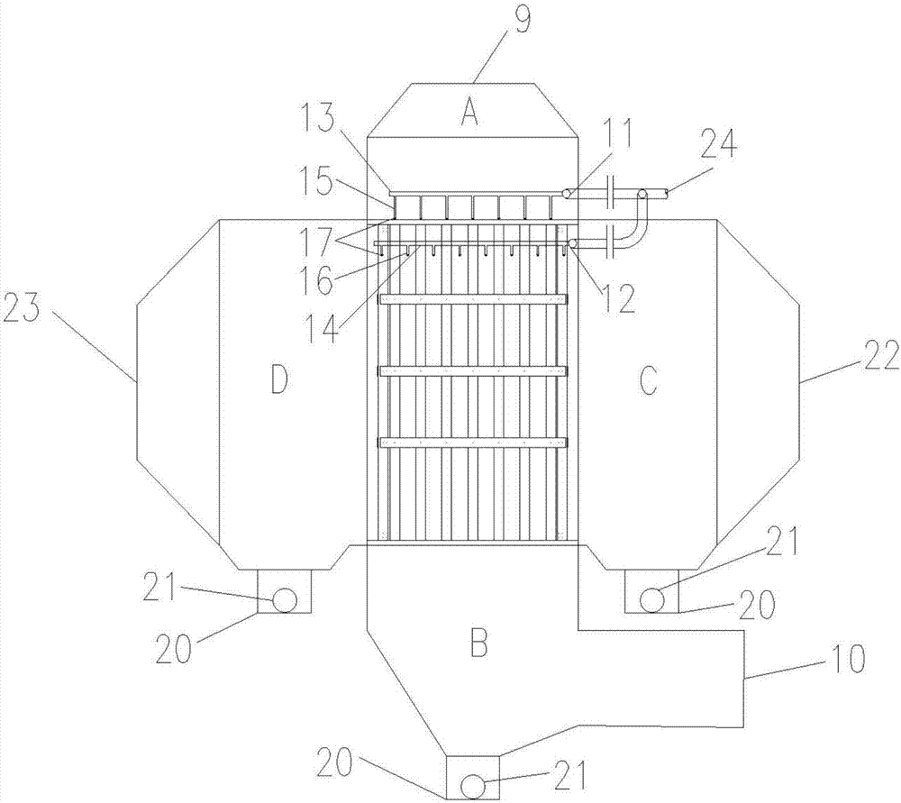
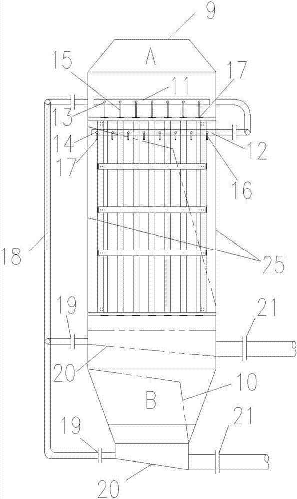
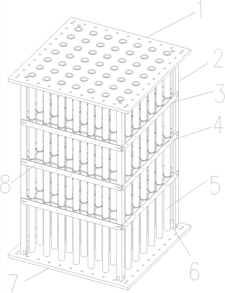
[0061] Such as Figure 1 ~ Figure 4 As shown, the shell-and-tube fluoroplastic flue gas-flue gas heat exchanger K of the present invention includes a heat exchanger shell 25, a heat exchange tube 5 and a supporting device.

[0062] The heat exchanger housing 25 includes a vertical raw flue gas flue and a horizontal clean flue gas flue. A plurality of heat exchange tubes 5 are vertically arranged along the direction of the raw flue gas flue to form a heat exchange tube grid, and are fixed in the heat exchanger shell 25 by a supporting device.

[0063] Among them, the raw flue gas flows vertically in the tube of the heat exchange tube 5 of the heat exchange tube grid, and the clean flue gas flows horizontally outside the tube of the heat exchange tube 5 of the heat exchange tube grid, so that the flow of the raw flue gas and the clean flue gas directions perpendicular to each other.

[0...


PUM

PropertyMeasurementUnit
thicknessaaaaaaaaaa

Abstract

The invention belongs to the technical field of industrial energy conservation and environmental protection, and particularly relates to a tube nest type fluoroplastic flue gas-flue gas heat exchanger. The tube nest type fluoroplastic flue gas-flue gas heat exchanger comprises a heat exchanger shell, heat exchange pipes and a supporting device, wherein the heat exchanger shell comprises a vertical untreated flue gas flue and a horizontal purified flue gas flue; the plurality of heat exchange pipes are vertically arranged along the direction of the untreated flue gas flue to form heat exchange pipe railings and are fixed in the heat exchanger shell by the supporting device; and untreated flue gas vertically flows in the heat exchange pipes of the heat exchange pipe railings, purified flue gas horizontally flows outside the heat exchange pipes of the heat exchange pipe railings, and therefore, the flow directions of the untreated flue gas and the purified flue gas are perpendicular to each other. The tube nest type fluoroplastic flue gas-flue gas heat exchanger is applied to high energy-consuming industries such as electric power, building materials and metallurgy, operates at an outlet of a wet desulphurization device, and recycles heat of untreated flue gas at a flue gas inlet of the wet desulphurization device to heat purified flue gas at a flue gas outlet of the wet desulphurization device, thereby increasing the dispersive capacity and emitting height of flue gas emitted by a chimney and eliminating industrially frequent gypsum rain and white smoke phenomenon.

Description

technical field [0001] The invention belongs to the technical field of industrial energy saving and environmental protection, and in particular relates to a tubular fluoroplastic flue gas-flue gas heat exchanger, which can be used for heating up and discharging the net flue gas after a wet desulfurization device. Background technique [0002] China's coal-based energy structure has resulted in domestic power sources being dominated by coal-fired thermal power generation. At the end of 2010, the installed capacity of power generation in my country reached about 950 million kilowatts, of which the installed capacity of thermal power generation was 700 million kilowatts, accounting for about 73.68% of the total capacity. [0003] In order to solve the problem of boiler flue gas emission pollution, coal-fired power plants have adopted a large number of technical measures in recent years to reduce smoke, SO 2 , nitrogen oxides and other pollutants, the electrostatic precipitator...

Claims


Application Information

Patent Timeline
Patent Type & Authority Applications(China)
IPC IPC(8): F28D7/16F28F21/06F28F21/00F28F21/08F28F9/013F28G9/00F23J15/08
CPCF28D7/1653F23J15/08F23J2215/20F23J2900/15081F28F9/013F28F21/006F28F21/062F28F21/083F28G9/00
Inventor 赵禹高建民
Owner 北京新世翼节能环保科技股份有限公司
Why Eureka
Try Eureka