Liquid level sensor system based on monomode -multimode-monomode optical fiber structure and Bragg gratings

A fiber optic Bragg and liquid level sensor technology, which is applied in the direction of converting sensor output, using optical devices to transmit sensing components, liquid level indicators, etc., can solve the problem that the cladding mode reflection spectrum is not easy to obtain, etc.

Pending Publication Date: 2017-08-18
CHINA JILIANG UNIV
1 Cites 1 Cited by

AI-Extracted Technical Summary

Problems solved by technology

[0004] Patent CN 203981244 U discloses a liquid level sensor based on a thin-core tilted fiber grating, which can accurately measure the change of the liquid level by changing the reflection spectrum of the thin-core tilted fiber grating, but the measured liquid The material is limited ...

Abstract

A liquid level sensor system based on a monomode-multimode-monomode optical fiber structure and Bragg gratings comprises an electric linear platform, a temperature control platform, a water container, an optical fiber group, a circulator, a broadband light source and a spectrograph. The optical fiber group comprises first monomode optical fibers, second monomode optical fibers, multimode optical fibers and the Bragg gratings etched on the second monomode optical fibers, and is fixed vertically according to the sequence of the first monomode optical fibers, the multimode optical fibers and the second monomode optical fibers. The optical fiber group is soaked in the water container. The electric linear platform is connected with the optical fiber group through a support. The water container is arranged on the temperature platform. The optical fiber group is connected with the circulator. The circulator is connected with the broadband light source and the spectrograph clockwise. The liquid level sensor system has the advantages that the central wavelength of the Bragg gratings is positioned in a filter spectrum area at the edge of a sensor, and a Bragg grating reflection spectrogram is determined to measure the liquid level, so that operability and sensitivity are high, structure is simple and loss is low.

Application Domain

Machines/enginesLevel indicators +2

Technology Topic

Light sourceLiquid level sensor +12

Image

  • Liquid level sensor system based on monomode -multimode-monomode optical fiber structure and Bragg gratings
  • Liquid level sensor system based on monomode -multimode-monomode optical fiber structure and Bragg gratings

Examples

  • Experimental program(1)

Example Embodiment

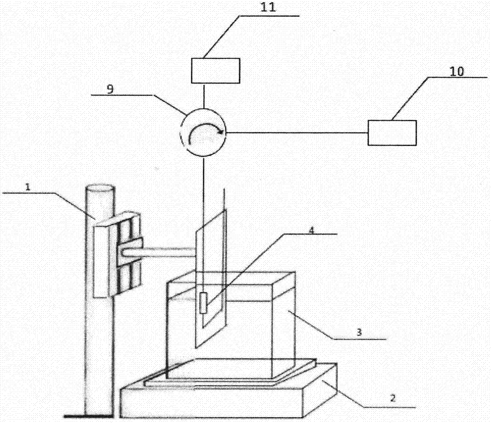
[0014] figure 1 In the present invention, a liquid level sensor system based on a single-mode-multi-mode-single-mode optical fiber structure and a Bragg grating includes an electric linear stage 1, a temperature control stage 2, a water container 3, and an optical fiber group 4. The optical fiber group 4 Immerse in the water container 3, at the same time connect the electric linear stage 1 with the optical fiber group 4 through the bracket, the water container 3 is placed on the temperature control table 2, the optical fiber group 4 is connected with the circulator 9, the circulator 9 is connected with the spectrometer 10 and The broadband light sources 11 are connected in a clockwise direction.
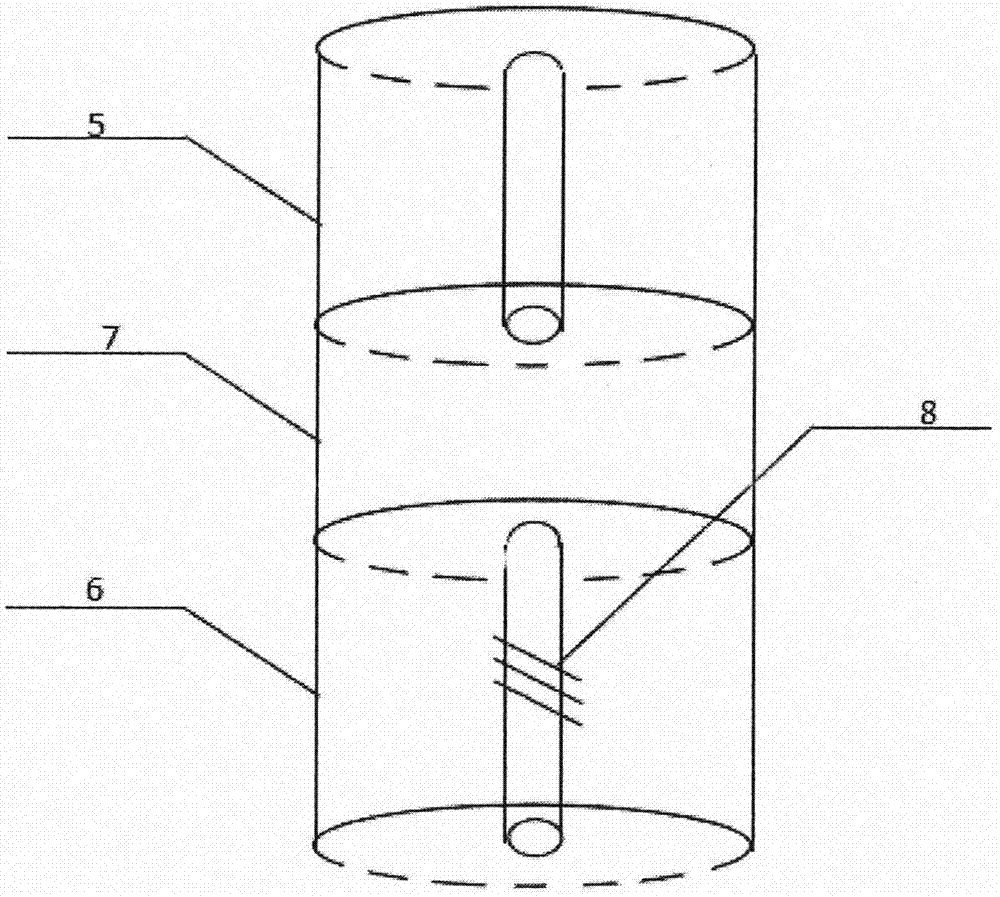
[0015] figure 2 In a liquid level sensor system based on a single-mode-multi-mode-single-mode fiber structure and a Bragg grating of the present invention, the structure of the fiber group 4 consists of a first single-mode fiber 5, a second single-mode fiber 6, a multi-mode fiber 7 and The Bragg grating 8 engraved on the second single-mode fiber 6 is composed of the first single-mode fiber 5-multi-mode fiber 7-second single-mode fiber 6 in the vertical direction, the lower part is used as a transmission outlet, and the upper part is Reflect the entrance and exit.

PUM

PropertyMeasurementUnit
Length3.0mm
Diameter125.0µm
Length58.2mm

Description & Claims & Application Information

We can also present the details of the Description, Claims and Application information to help users get a comprehensive understanding of the technical details of the patent, such as background art, summary of invention, brief description of drawings, description of embodiments, and other original content. On the other hand, users can also determine the specific scope of protection of the technology through the list of claims; as well as understand the changes in the life cycle of the technology with the presentation of the patent timeline. Login to view more.
Why Eureka
Try Eureka