
Multi-layer solid wood floor forming device

A molding device, a technology for solid wood floors, applied in tenon-making devices, jointing of wooden veneers, adhesive application devices, etc., can solve the problems of floor warping, low production efficiency, affecting bonding effect, etc., and achieve uniform distribution of glue , Improve molding efficiency, good bonding effect

Inactive Publication Date: 2017-08-22
湖州红树叶木业有限公司
View PDF0 Cites 6 Cited by
  • Summary
  • Abstract
  • Description
  • Claims
  • Application Information

AI Technical Summary

Problems solved by technology

[0015] The existing hot pressing method is to bond the multi-layer boards with environmental protection glue, and then carry out hot pressing in a hot press to form a shape. The disadvantage of this method is that the application of the environmental protection glue is not uniform enough, which will lead to different bonding degrees. will cause the floor to warp
One-time hot pressing in the hot press may cause bubbles in the bonding of each layer, and the gas in the bubbles escapes during hot pressing, resulting in no glue at the place and affecting the bonding effect
[0016] Existing multi-layer solid wood floor slabs need to be transferred to other stations for processing after hot pressing, which cannot be done continuously and the production efficiency is low

Method used


Image

  • Multi-layer solid wood floor forming device
  • Multi-layer solid wood floor forming device
  • Multi-layer solid wood floor forming device

Examples


Embodiment Construction

[0040] The present invention will be further described below in conjunction with the embodiments, and the described embodiments are only a part of the embodiments of the present invention, not all of them. Based on the embodiments of the present invention, other used embodiments obtained by persons of ordinary skill in the art without creative efforts all belong to the protection scope of the present invention.

[0041] The present invention includes a conveying mechanism 1, a plate feeding mechanism 2, a glue brushing mechanism 3 and a drying mechanism 4, a vertical grooving mechanism 5, a steering mechanism 6 and a horizontal grooving mechanism 7. The plate feeding mechanism 2 has nine sets, and the The glue brushing mechanism 3 has eight sets, and the plate feeding mechanism 2 and the glue brushing mechanism 3 are arranged at intervals. According to the conveying direction of the conveying mechanism 1, the first set of plate feeding mechanism 2 is located in front of the fir...


PUM


Abstract

The invention discloses a multi-layer solid wood floor forming device, which is characterized in that it comprises a conveying mechanism, a plate feeding mechanism, a glue brushing mechanism, a drying mechanism, a vertical groove cutting mechanism, a steering mechanism and a transverse groove cutting mechanism There are nine sets of plate mechanisms, and eight sets of the glue brushing mechanism. The plate feeding mechanism and the glue brushing mechanism are arranged at intervals. According to the conveying direction of the conveying mechanism, the first set of plate feeding mechanisms is located in front of the first set of glue brushing mechanisms. The plate feeding mechanism is installed on the side of the conveying mechanism, the glue brushing mechanism spans above the conveying mechanism, the drying mechanism is located behind the last set of plate conveying mechanism, and the vertical grooving mechanism is located behind the dryer , the steering mechanism is located behind the vertical grooving mechanism, the transverse grooving mechanism is located behind the steering mechanism, and a heater is installed inside the rubber brushing roller of the gluing mechanism. The invention bonds multiple layers of solid wood together without air bubbles at the bonding place, and the glue is evenly applied to prevent the floor from warping, and can operate continuously, thereby improving the forming efficiency.

Description

technical field [0001] The invention relates to a multi-layer solid wood floor manufacturing device, in particular to a multi-layer solid wood floor continuous molding device. Background technique [0002] The multi-layer solid wood floor is based on the multi-layer boards arranged in a criss-cross pattern, and the high-quality precious wood is selected as the panel. After being coated with resin glue, it is made by high temperature and high pressure in a hot press. It is not easy to deform and crack, has a very small shrinkage and expansion coefficient, and has a good ability to adjust indoor temperature and humidity. The surface layer can show the natural wood grain of the wood. The paving is simple and has a wide range of applications. The price is higher than composite flooring and lower than solid wood flooring. Suitable for geothermal heating room installation. Its specific manufacturing steps are: [0003] Step 1: log selection Only good split wood can produce a go...

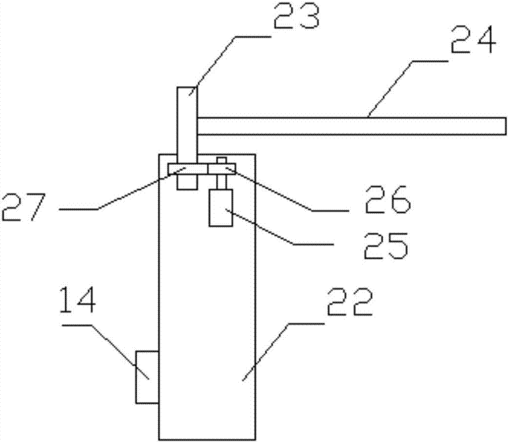
Claims


Application Information

Patent Timeline
IPC IPC(8): B27M3/04B27G11/00B27G11/02B27D5/00B27D1/08B27F1/08
CPCB27M3/04B27D1/08B27D5/00B27F1/08B27G11/00B27G11/02
Inventor 张碧金
Owner 湖州红树叶木业有限公司
Learn More