Heat-pipe-type heat energy recycling and cooling device and system

A heat recovery and cooling device technology, applied in heat storage equipment, indirect heat exchangers, heat exchanger types, etc., can solve the problems of high manufacturing cost, uneconomical operation cost, and poor thermal conductivity of corrugated heat exchange fins, and achieve High heat recovery efficiency, excellent thermal conductivity, flexible and convenient installation

Pending Publication Date: 2017-08-22
南通海鹰机电集团有限公司
View PDF8 Cites 0 Cited by
  • Summary
  • Abstract
  • Description
  • Claims
  • Application Information

AI Technical Summary

Problems solved by technology

However, practice has proved that this technical solution has the following defects: 1) The thermal conductivity of the corrugated heat exchanger is much worse than that of the heat pipe; 2) There are gas channels between adjacent corrugated heat exchangers, and the wind resistance is large when the exhaust gas passes through; 3) The corrugated heat exchanger Sheet manufacturing cost is high, installation trouble, and not suitable for liquid heat exchange
The disadvantages of this technical solution are: 1) a water distribution device is required to recover the heat exhausted from the air conditioner, which increases the cost; 2) the water distribution device consumes energy and the operating cost is uneconomical; 3) it cannot meet the heat exchange requirements of various fluid media

Method used


Image

  • Heat-pipe-type heat energy recycling and cooling device and system
  • Heat-pipe-type heat energy recycling and cooling device and system
  • Heat-pipe-type heat energy recycling and cooling device and system

Examples


Embodiment Construction

[0027] In order to make the purpose, technical solution and advantages of the present invention clearer, the present invention will be further described in detail below in conjunction with the embodiments and accompanying drawings.

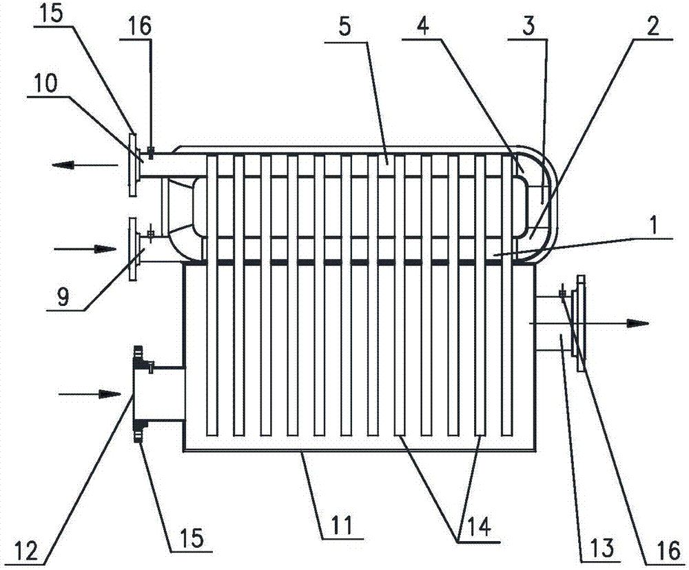
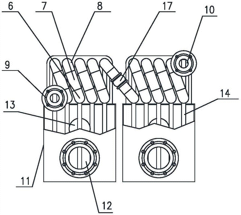
[0028] refer to figure 1 , figure 2 As shown, a heat pipe type heat energy recovery cooling device of the present invention includes a coil assembly, a heat exchange box 11 and a heat conduction member 14. A waste heat medium is passed into the coil assembly, and the waste heat medium can be gas or liquid, etc. for heat exchange The heat-absorbing medium is passed into the box 11, and the heat-absorbing medium can be gas or liquid, etc., and the heat-conducting component 14 is connected to the coil assembly and the heat exchange box 11, thereby transferring the heat of the waste heat medium to the heat exchange box 11, and utilizing the waste heat Heat the heat-absorbing medium of the heat exchange box 11, the heat-absorbing medium can be direct...


PUM


Abstract

The invention discloses a heat-pipe-type heat energy recycling and cooling device. The heat-pipe-type heat energy recycling and cooling device comprises a coil pipe assembly, heat exchange boxes and heat conducting parts. The coil pipe assembly is tubular and comprises a plurality of coil pipe units. The coil pipe units comprise first straight sections, longitudinal sections and second straight sections, wherein the first straight sections extend in the transverse direction; one ends of the longitudinal sections are connected with the first straight sections, and the longitudinal sections perpendicularly extend in the longitudinal direction; and the second straight sections are connected with the other ends of the longitudinal sections and the second straight sections extend in the transverse direction. All the coil pipe units are connected through oblique-straight sections which obliquely extend in the longitudinal direction. The first coil pipe unit forms a coil pipe inlet of the coil pipe assembly, and the last coil pipe unit forms a coil pipe outlet of the coil pipe assembly. The heat exchange boxes are located below the coil pipe assembly and are provided with heat exchange inlets and heat exchange outlets. The multiple heat conducting parts penetrate into the first straight sections and the second straight sections of the coil pipe units as well as the heat exchange boxes. In addition, the invention discloses a heat-pipe-type heat energy recycling and cooling system. The heat-pipe-type heat energy recycling and cooling device and system are high in efficiency, low in cost and wide in application range.

Description

technical field [0001] The present invention relates to the technical field of heat exchange devices, in particular, the present invention relates to a heat pipe type heat energy recovery cooling device and a heat pipe type heat energy recovery cooling system. Background technique [0002] In the industrial production of many industries such as metallurgy and chemical industry, there is a large amount of waste heat that needs to be discharged. The direct discharge of these waste heat or the use of temperature difference cycle cooling not only cause adverse effects on the environment, but also waste energy. [0003] It can be seen through retrieval that the Chinese patent application number CN200820061805.7 discloses a waste gas waste heat recovery heat exchanger, including a heat exchanger and a deflector; the heat exchanger includes a heat exchanger shell and a corrugated heat exchange fin; The shell of the heat exchanger is a cuboid structure with open upper and lower ends...

Claims


Application Information

Patent Timeline
Patent Type & Authority Applications(China)
IPC IPC(8): F28D15/02F28D20/00
CPCF28D15/02F28D20/00Y02E60/14
Inventor 杨裕能
Owner 南通海鹰机电集团有限公司
Why Eureka
Try Eureka